Rotor pump convenient to overhaul and using method thereof

A rotor pump and rotor technology, which is applied in the field of rotor pumps that are easy to maintain, can solve the problems of inconvenient disassembly of the rotor and the main shaft, achieve good practical value, realize the sealing effect, and ensure the effect of normal use.

Active Publication Date: 2020-04-28
ANHUI HUAYI STAINLESS STEEL CONTAINER CO LTD
View PDF6 Cites 0 Cited by
  • Summary
  • Abstract
  • Description
  • Claims
  • Application Information

AI Technical Summary

Problems solved by technology

[0004] The purpose of the present invention is to provide a rotor pump that is easy to overhaul and its use method, so as to solve the problem of inconvenient disassembly of the rotor and the main shaft proposed in the above-mentioned background technology

Method used


Image

  • Rotor pump convenient to overhaul and using method thereof
  • Rotor pump convenient to overhaul and using method thereof
  • Rotor pump convenient to overhaul and using method thereof

Examples


Embodiment 1

[0031] see figure 1 , figure 2 , image 3 , Figure 4 , Figure 5 , Figure 6 and Figure 7 , the present invention provides a technical solution:

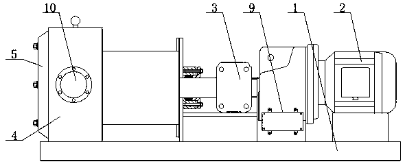
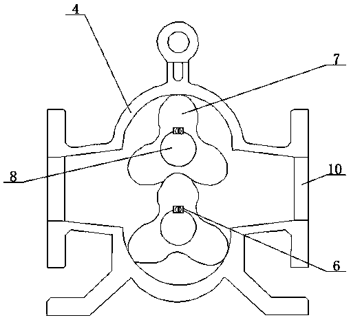
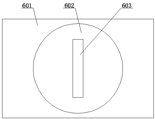
[0032] A rotor pump for easy maintenance and its use method, comprising a base 1 and a motor 2, the upper end of the base 1 is fixedly connected with a motor 2 and a pump casing 4 distributed left and right, the end of the main shaft of the motor 2 is fixedly connected with a shaft coupling 3, the coupling The other side of the shaft device 3 is fixedly connected with the pump casing 4, the front and rear sides of the pump casing 4 are provided with through holes 10, the left end of the pump casing 4 is fixedly connected with the casing 5, and the inner side of the pump casing 4 is rotatably connected with the main shaft 8 distributed up and down , the outside of the main shaft 8 is provided with a key mechanism 6, the key mechanism 6 includes a key body 601 and a rotating ring 602, the left end surface of the key body 601 ...

Embodiment 2

[0040] In embodiment 2, the same parts as embodiment 1 will not be repeated. The difference is that when the shell 5 is disassembled, cracks are found on the surface of the rotor 7 and the main shaft 8, and it needs to be repaired at this time, because the key body Under the effect of 601, it is not easy to disassemble. At this time, insert a screwdriver into the limiting groove 603, and then rotate the rotating ring 602. The rotating ring 602 drives the threaded rod 604 to rotate, and the threaded rod 604 drives the limiting plate 605 to rotate, so that the rotating ring 602 and the The key body 601 is separated, and the set limit plate 605 prevents the threaded rod 604 from breaking away from the key body 601 during use. At this time, by using the rotating ring 602 and the threaded rod 604 as a point of leverage, it is easy to remove the key body 601 from The rotor 7 is separated from the main shaft 8, which is very convenient for the replacement and maintenance of the rotor ...


PUM


Abstract

The invention relates to the technical field of rotor pumps, in particular to a rotor pump convenient to overhaul and a using method thereof. The rotor pump comprises a base and a motor, the motor anda pump shell which are distributed left and right are fixedly connected to the upper end face of the base, the tail end of a main shaft of the motor is fixedly connected with a coupling, the other side of the coupling is fixedly connected with the pump shell, the front and back sides of the pump shell are provided with through holes, the left end face of the pump shell is fixedly connected with ahousing, the inner side of the pump shell is rotatably connected with main shafts which are distributed up and down, and the outer sides of the main shafts are provided with key mechanisms. Each keymechanism comprises a key and a rotating ring, wherein the left end face of the key is provided with the rotating ring, and the right end face of the rotating ring is fixedly connected with a threadedrod. In the rotor pump, through the arrangement of the keys, the rotating rings, the threaded rods, limiting plates and grooves, during disassembly, the rotating rings are rotated through the grooves, so that the threaded rods rotate outwards, then the keys can be taken out through the rotating rings and the threaded rods, and the maintenance work of the rotor pump is facilitated.

Description

technical field [0001] The invention relates to the technical field of rotor pumps, in particular to a rotor pump which is convenient for maintenance and a method for using the same. Background technique [0002] Rotor pumps are also called colloid pumps, cam pumps, three-lobe pumps, universal delivery pumps, etc. Rotor pumps belong to positive displacement pumps, which achieve the purpose of delivering fluid by means of the periodic conversion of multiple fixed volume delivery units in the working chamber. Yes, the mechanical energy of the motor is directly converted into the pressure energy of the conveying fluid through the pump, and the flow rate of the pump only depends on the volume change value of the working chamber and its change frequency per unit time, and has nothing to do with the discharge pressure; The above is through a pair of synchronously rotating rotors, which are driven by a pair of synchronous gears in the box. Driven by the main and auxiliary shafts, t...

Claims


Application Information

Patent Timeline
IPC IPC(8): F04C2/12F04C11/00F04C15/00H02K5/22
CPCF04C2/12F04C11/008F04C15/0076F04C15/00H02K5/225
Inventor 李天昊
Owner ANHUI HUAYI STAINLESS STEEL CONTAINER CO LTD
Why Eureka
Try Eureka