Split type valve with anti-seismic function

A split type, valve technology, applied in valve details, multi-way valves, valve devices, etc., can solve the problems of poor airtightness and reliability, and achieve the effect of improving airtightness, facilitating disassembly and maintenance, and strengthening airtightness

Inactive Publication Date: 2020-04-28
陈艳艳
View PDF1 Cites 4 Cited by
  • Summary
  • Abstract
  • Description
  • Claims
  • Application Information

AI Technical Summary

Problems solved by technology

The valve body in the above patent has the following disadvantages: the valve body only relies on the opening and closing of the valve plate to realize the on-off of the valve, and the airtightness and reliability are poor

Method used


Image

  • Split type valve with anti-seismic function
  • Split type valve with anti-seismic function
  • Split type valve with anti-seismic function

Examples


Embodiment 1

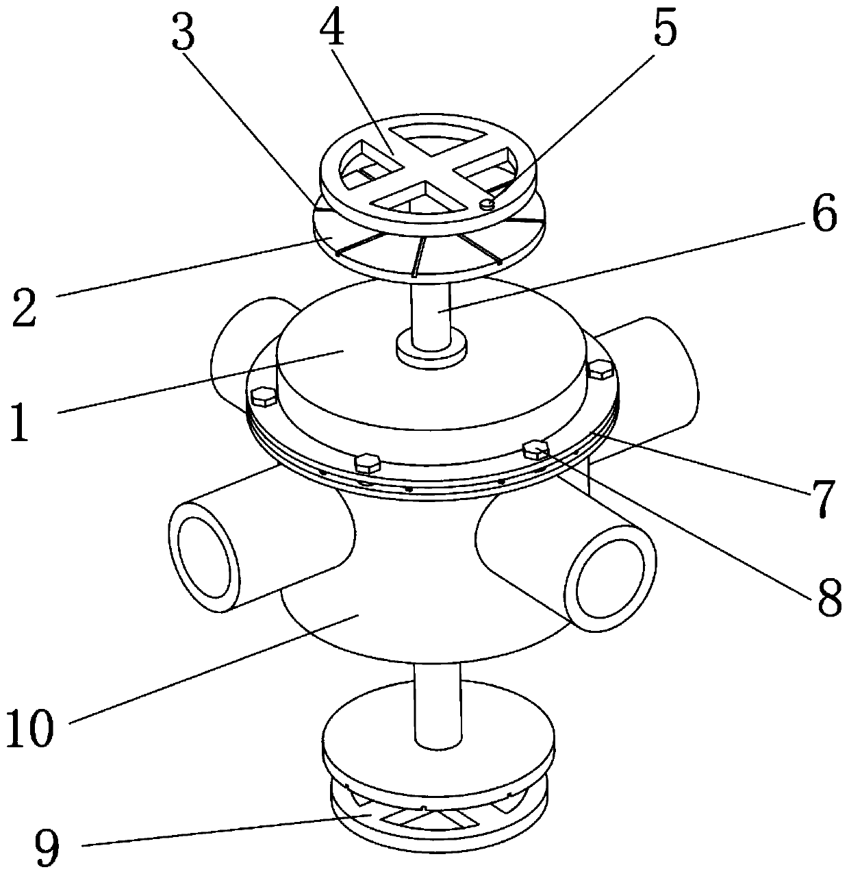
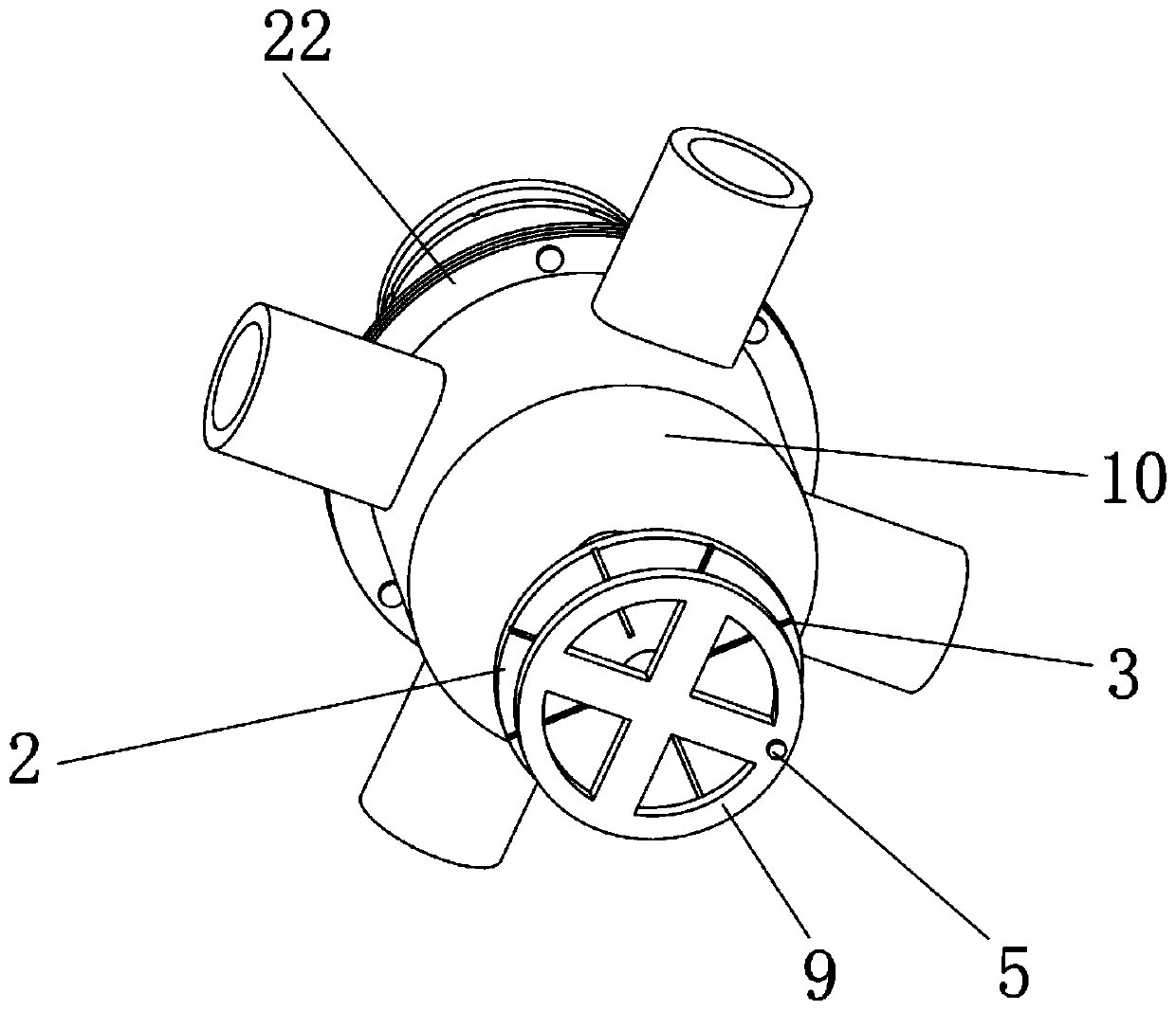
[0033] A split valve with anti-vibration function, such as figure 1 , Figure 4 , Figure 5 As shown, it includes a first valve body 1, a second valve body 10 and a conduction structure. The outer surface of the first valve body 1 is welded with a first connecting plate 7, and the outer surface of the second valve body 10 is welded with a second Connecting plate 22, the inner wall of the first connecting plate 7 and the inner wall of the second connecting plate 22 are connected with the same group of uniformly circumferentially distributed locking bolts 8 by threads; the outer wall of the top of the first valve body 1 and the second valve body 10 Two bearing blocks 25 are respectively fixed on the outer wall of the bottom of the bottom by screws, two control shaft seats 6 are respectively fixed on the outer walls of the two bearing blocks 25 by screws, and two control shaft seats 6 are slidingly connected on the inner walls of the two control shaft seats 6 respectively. One ...

Embodiment 2

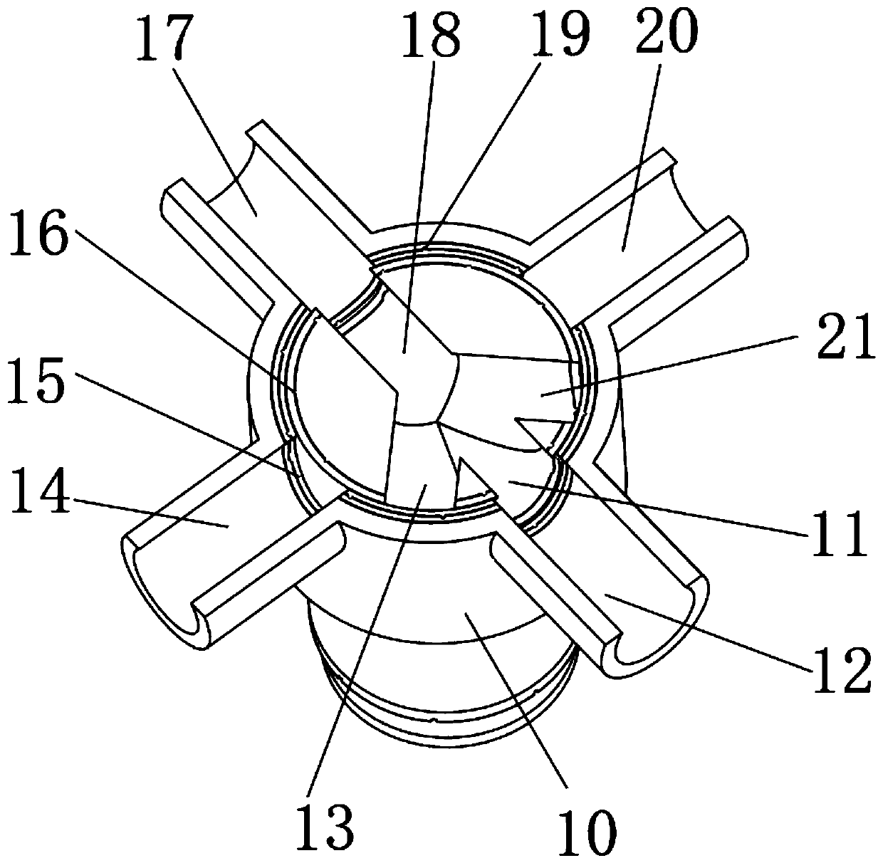
[0044] A split valve with anti-vibration function, such as figure 2 As shown, in order to solve the problem of firmness between the sealing layer and the valve core; this embodiment makes the following improvements on the basis of Embodiment 1: the outer surface of the first valve core 23 is provided with first protrusions uniformly distributed around the circumference 16, the outer surface of the second valve core 28 is provided with second protrusions 19 uniformly distributed around the circumference.

[0045] When this embodiment is in use, the first protrusion 16 can increase the contact area between the first sealing layer 27 and the first valve core 23, thereby increasing the firmness of the connection between the two; the second protrusion 19 can increase the second sealing The contact area between the layer 29 and the second valve core 28 increases the firmness of the connection between the two.


PUM


Abstract

The invention discloses a split type valve with an anti-seismic function, and relates to the technical field of valves. The split type valve aims to solve the problem that the sealing performance is poor. The split type valve specifically comprises a first valve body, a second valve body and a conduction structure, wherein a first connecting plate is welded to the outer surface of the first valvebody, a second connecting plate is welded to the outer surface of the second valve body, and the inner wall of the first connecting plate and the inner wall of the second connecting plate are connected with the same group of locking bolts which are uniformly distributed in the circumferential direction through threads; and two bearing seats are fixed on the outer wall of the top of the first valvebody and the outer wall of the bottom of the second valve body through screws correspondingly. According to the split type valve, the first valve body and the second valve body are arranged, so thatdisassembly and maintenance can be facilitated, and replacement of parts is facilitated; a first valve core and a second valve core are arranged, so that the function of multi-closing control can be realized, and the reliability is improved; and through holes, four joints and four channels are arranged, so that the function of multi-channel control can be realized, and the practicability is improved.

Description

technical field [0001] The invention relates to the technical field of valves, in particular to a split valve with anti-shock function. Background technique [0002] Valves are an essential and important part of fluid delivery systems. They are the main means for people to control fluid transportation on-off, adjustment, diversion, etc. With the continuous development of the valve industry, the functionality and reliability of valves are also constantly improving. . [0003] After searching, the Chinese patent application number is CN201822122610.5, which discloses a split valve, which includes two split parts of the valve body, a valve plate, a connecting shaft and a driving mechanism. Removably connected to form a complete valve body body, the formed valve body body has a cylindrical structure with a hollow part, the valve plate is limited to the hollow part of the formed valve body body, and the connecting shaft is installed on the valve body On the main body, the valve...

Claims


Application Information

Patent Timeline
Patent Type & Authority Applications(China)
IPC IPC(8): F16K11/20F16K37/00F16K27/06F16K27/10F16K5/04F16K5/08
CPCF16K5/0442F16K5/08F16K11/207F16K27/065F16K27/107F16K37/0016
Inventor 陈艳艳
Owner 陈艳艳
Why Eureka
Try Eureka