Optimization device and control method of optimization device

A technology for optimizing devices and control methods, applied in adaptive control, general control systems, control/regulation systems, etc., can solve problems such as time-consuming

Active Publication Date: 2020-04-28
FUJITSU LTD
View PDF6 Cites 2 Cited by
  • Summary
  • Abstract
  • Description
  • Claims
  • Application Information

AI Technical Summary

Problems solved by technology

State transitions take time due to energy barriers generated against k-hot constrained terms
According to the above, in the optimization device in

Method used


Image

  • Optimization device and control method of optimization device
  • Optimization device and control method of optimization device
  • Optimization device and control method of optimization device

Examples


no. 1 approach

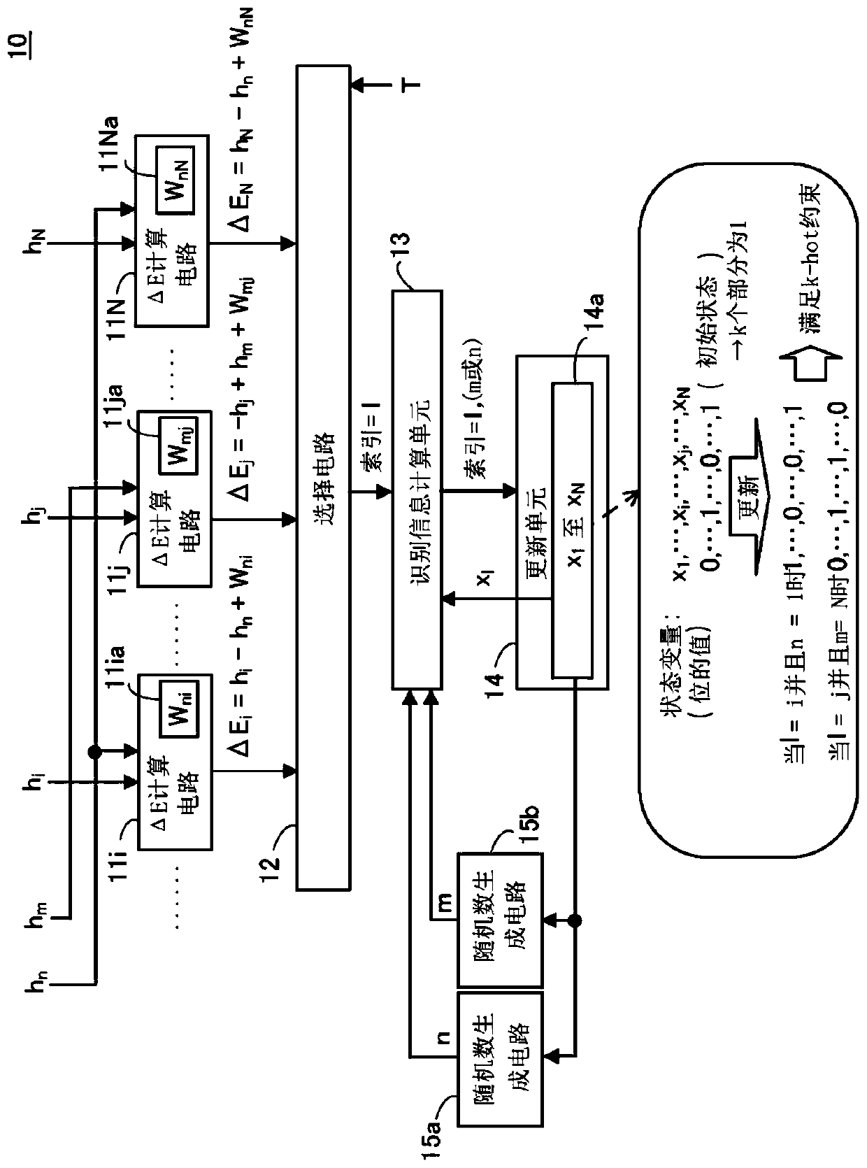
[0047] figure 1 is a diagram showing an example of the optimization device according to the first embodiment.

[0048] The optimization device 10 includes N ΔE calculation circuits (for example, including figure 1 ΔE calculation circuits 11i, 11j, and 11N), selection circuit 12, identification information calculation unit 13, update unit 14, and random number generation circuits 15a and 15b.

[0049] Among the N ΔE calculation circuits, k (k>1) ΔE calculation circuits ( figure 1 The ΔE calculation circuits 11i and 11N in the example in , etc.) execute the following processing.

[0050] Among the N bits, the local field value (for example, h i and h N ) is supplied to each of the k ΔE calculation circuits. Local field value (h n ) is supplied to each of the k ΔE calculation circuits. exist figure 1 In , the circuit for calculating the local field value, the circuit for controlling the propagation of the local field value to the ΔE calculation circuit, etc. are not shown...

no. 2 approach

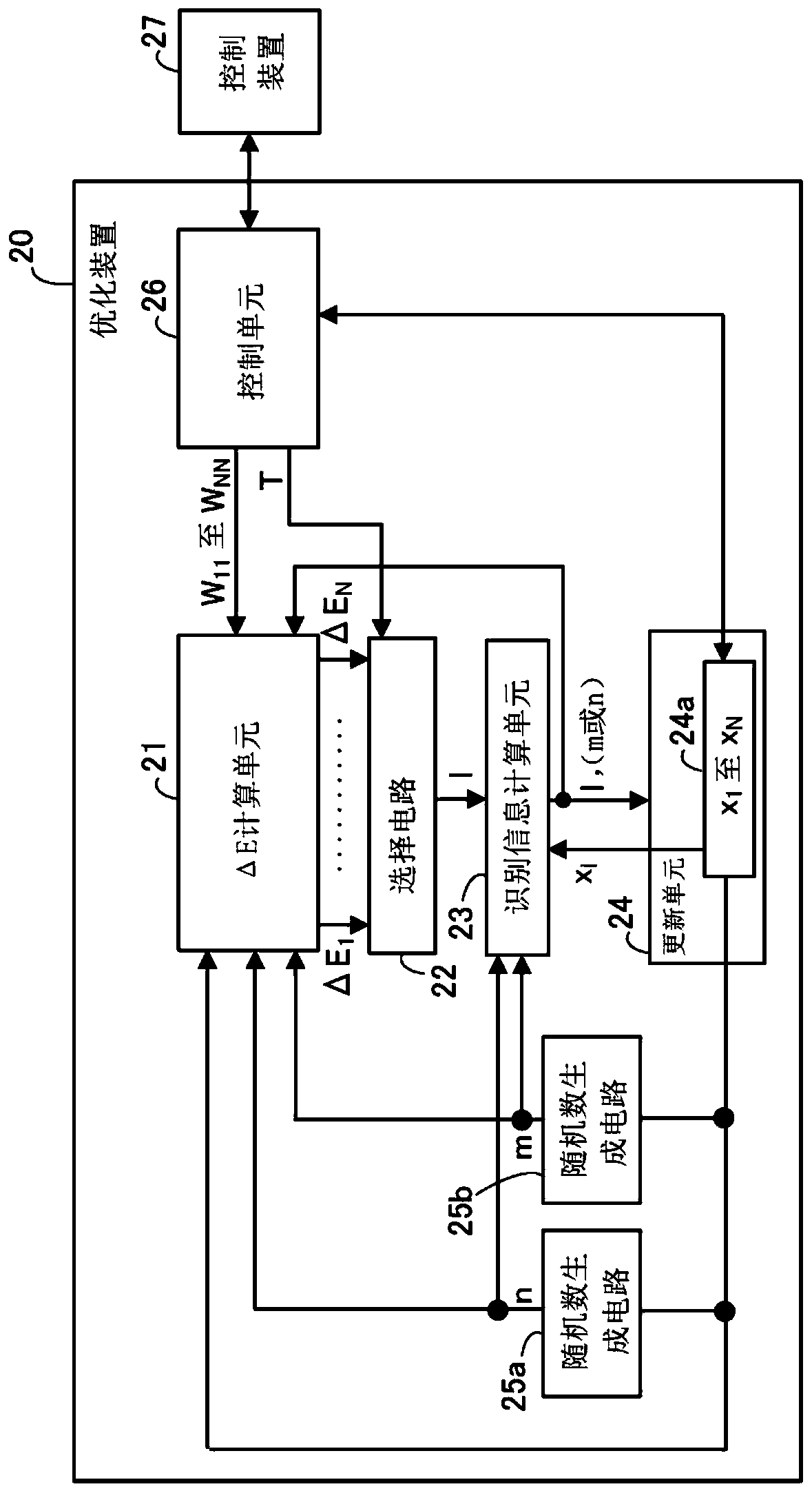
[0086] figure 2 is a diagram showing an example of an optimization device according to the second embodiment.

[0087] The optimization device 20 includes a ΔE calculation unit 21 , a selection circuit 22 , an identification information calculation unit 23 , an update unit 24 , random number generation circuits 25 a and 25 b , and a control unit 26 .

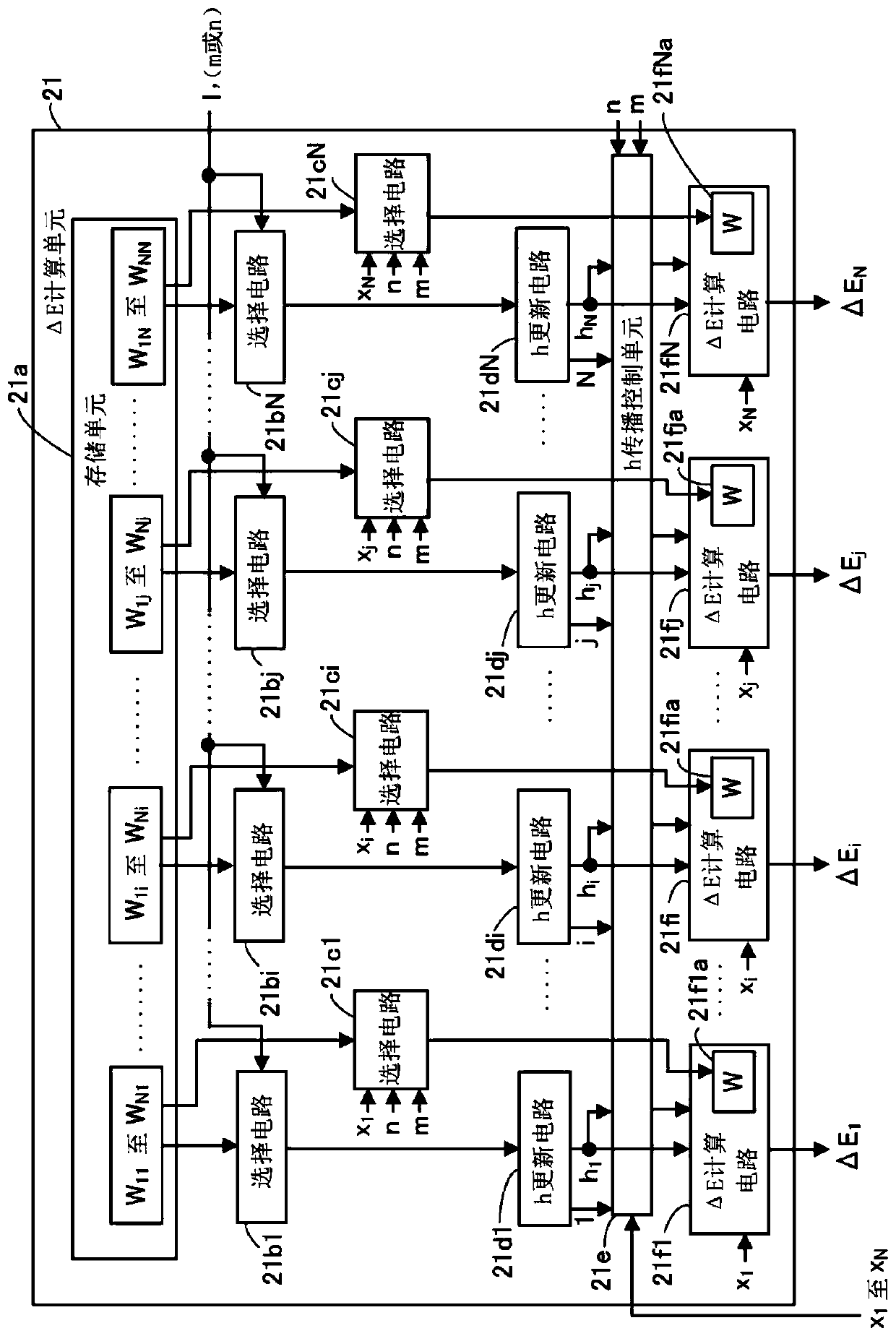
[0088] The ΔE calculation unit 21 calculates the energy change (ΔE 1 to ΔE N ).

[0089] Based on thermal excitation energy and ΔE 1 to ΔE N The selection circuit 22 outputs an index=1 identifying a bit having a value that is allowed to be updated among the N bits. The thermal excitation energy is determined based on the random number and T input from the control unit 26 . In some cases, according to the thermal excitation energy and ΔE 1 to ΔE NThe size relationship between even for one of the N bits does not allow updates. Assume that the selection circuit 22 outputs a flag indicating whether updating is permitted. ...


PUM


Abstract

The application provides an optimization device and a control method of the optimization device. The optimization device includes: k first calculation circuits, N-k second calculation circuits, a selection circuit, an identification information calculation circuit and an update circuit. The first calculation circuit calculates a first energy change of an Ising model due to a change of a value of one of k first bits having values of 1 and a change of a value of a second bit having a value of 0 selected based on a generated first random number. The second calculation circuit calculates a secondenergy change of the Ising model due to a change of a value of one of (N-k) third bits having the values of 0 and a change of a value of a fourth bit having a value of 1 selected based on a generatedsecond random number.

Description

technical field [0001] Embodiments discussed herein relate to an optimization device and a method of controlling the optimization device. Background technique [0002] As a method for solving multivariable optimization problems that are not easily handled by a Neumann-type computer, there is an optimization device using an Ising-type energy function (also known as an Ising machine or a Boltzmann machine Case). The optimization means calculates the problem to be calculated by replacing the problem with an Ising model, which is a model representing the rotational behavior of the magnetic body. [0003] It is also possible to model the optimization device eg using a neural network. In this case, each of the bits corresponding to the number of rotations included in the Ising model acts as a neuron, with the neuron according to the other bit and the The weighted value of the size (also called the coupling factor) outputs 0 or 1. For example, the optimization device uses a pro...

Claims


Application Information

Patent Timeline
IPC IPC(8): G05B13/04
CPCG05B13/042G06N3/063G06N5/01G06N3/047G06N3/044G06N10/00G06F15/173G06F17/16G06N7/01
Inventor 神田浩一田村泰孝
Owner FUJITSU LTD
Why Eureka
Try Eureka