Eureka AIR delivers breakthrough ideas for toughest innovation challenges, trusted by R&D personnel around the world.

Optimization device and method for controlling optimization device

An optimization device and energy change technology, applied in general control systems, calculations using numerical representation, adaptive control, etc., can solve problems such as time-consuming

Active Publication Date: 2020-10-23
FUJITSU LTD
View PDF9 Cites 1 Cited by
  • Summary
  • Abstract
  • Description
  • Claims
  • Application Information

AI Technical Summary

Problems solved by technology

In summary, conventional optimization devices have the following problem: it takes time to compute an optimization problem with one-heat constraints (to search for a ground state)

Method used


Image

  • Optimization device and method for controlling optimization device
  • Optimization device and method for controlling optimization device
  • Optimization device and method for controlling optimization device

Examples


no. 1 approach

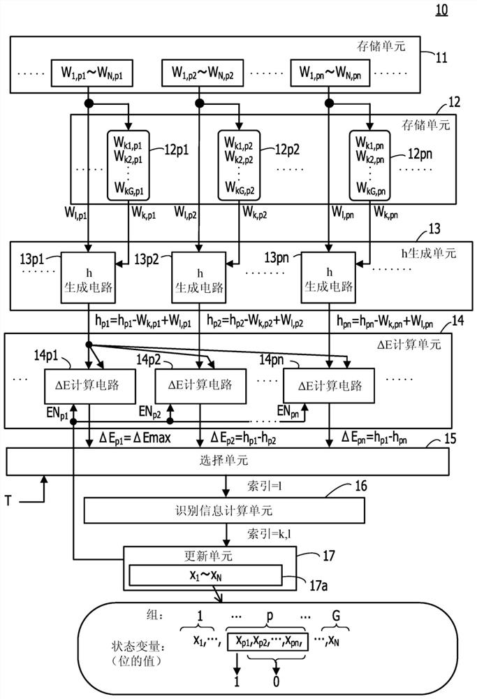
[0076] figure 1 is a diagram showing an example of the optimization device of the first embodiment.

[0077] The optimization device 10 includes storage units 11 and 12 , an h generation unit 13 , a ΔE calculation unit 14 , a selection circuit 15 , an identification information calculation unit 16 , and an update unit 17 .

[0078] Notice, figure 1 Shown is a circuit portion that, in the case where N bits are divided into G groups, calculates the value of the state transition due to Hamming distance=2 between a plurality of (n) bits included in the p-th group p energy changes that occur. exist figure 1 In , the illustration of the circuit part that calculates the energy change of other groups is omitted.

[0079] The storage unit 11 holds a matrix of weight values ​​indicating the magnitude of interaction between each of the N bits. During the initial setting process, a matrix of weight values ​​is stored in the storage unit 11 by a control unit (not shown). exist figur...

no. 2 approach

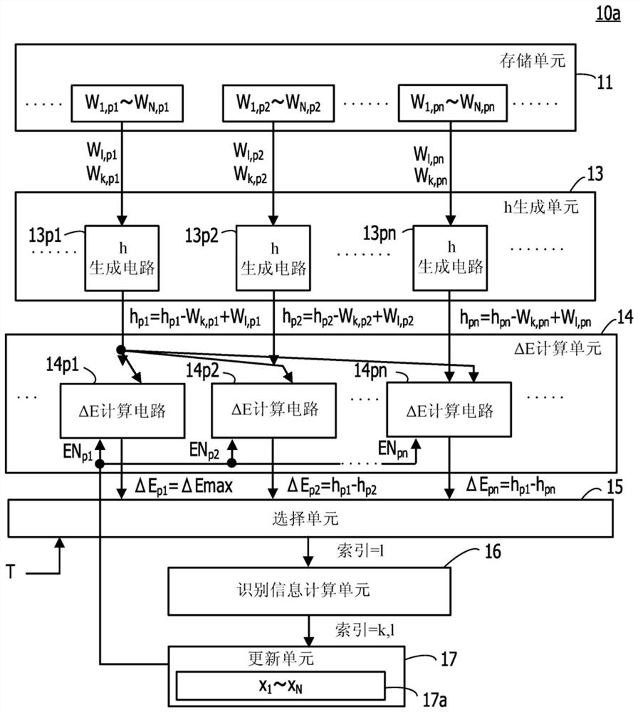
[0125] Figure 4 is a diagram showing an example of the optimization device of the second embodiment.

[0126] The optimization device 20 includes a calculation unit 21 , a selection circuit 22 , an identification information calculation unit 23 , an update unit 24 and a control unit 25 .

[0127] The calculation unit 21 calculates the energy when the transition from one state satisfying the one-heat constraint to another state satisfying the one-heat constraint is performed by a state transition with a Hamming distance=2 in each of the above-described G groups Change (ΔE 1 to ΔE N ).

[0128] The selection circuit 22 is based on the thermal excitation energy and ΔE 1 to ΔE N The index=1 for identifying a bit that allows the value to be updated from 0 to 1 is output from the bits whose values ​​are all 0 included in each of the groups 1 to G. The thermal excitation energy is determined based on random numbers and T input from the control unit 25 . Note that according to...


PUM


Abstract

The invention provides an optimization device and a method for controlling the optimization device. The optimization device comprises: a plurality of calculation circuits, each of which calculates, for a plurality of bits corresponding to a plurality of spins included in an Ising model obtained by converting a problem to be calculated, in a case where the plurality of bits is divided into a plurality of groups, on the basis of a first local field value for a first bit having a value of 1 and a second local field value for a second bit having a value of 0 among a plurality of bits included in each of the plurality of groups, a first energy change of the Ising model due to a change of the value of the first bit from 1 to 0 and a change of the value of the second bit from 0 to 1; a selectioncircuit that outputs first bit identification information on the basis of a magnitude relationship between the first energy change and thermal excitation energy determined on the basis of an input temperature parameter and a random number; an identification information calculation; an update unit; a second storage unit; and a local field generation unit.

Description

technical field [0001] The present embodiment relates to an optimization device and a method for controlling the optimization device. Background technique [0002] As a method of solving multivariable optimization problems, which von Neumann computers are not good at, there is an optimization device using an Ising energy function (sometimes called an Ising machine or a Boltzmann machine). The optimization device performs calculations by substituting an Ising model, which is a model representing spin behavior of a magnetic material, for a problem to be calculated. [0003] Optimizing means can also be modeled by using eg neural networks. In this case, each of the bits corresponding to the number of spins included in the Ising model acts as a neuron according to the The weight value of the size (also known as the coupling coefficient) and the value of the other bits output 0 or 1. The optimization means obtains a state (combination of values ​​of individual bits) in which t...

Claims


Application Information

Patent Timeline
Patent Type & Authority Applications(China)
IPC IPC(8): G05B13/04
CPCG05B13/042G06F7/48G06N10/00G06N5/01Y02T10/40G06N7/01G06F17/16G06F17/18G06F17/11
Inventor 神田浩一田村泰孝渡部康弘
Owner FUJITSU LTD
Why Eureka
Eureka Blog
Learn More