Liquid cooling head and liquid cooling type heat dissipation system
A liquid-cooled head and heat-dissipating unit technology, used in instruments, electrical digital data processing, electrical components, etc., can solve the problems of accelerating heat exchange, accelerating the collision of cooling fins, and turbulent manufacturing effects, so as to improve heat absorption. Efficiency, good heat dissipation effect
- Summary
- Abstract
- Description
- Claims
- Application Information
AI Technical Summary
Problems solved by technology
Method used
Image

Examples
Embodiment Construction
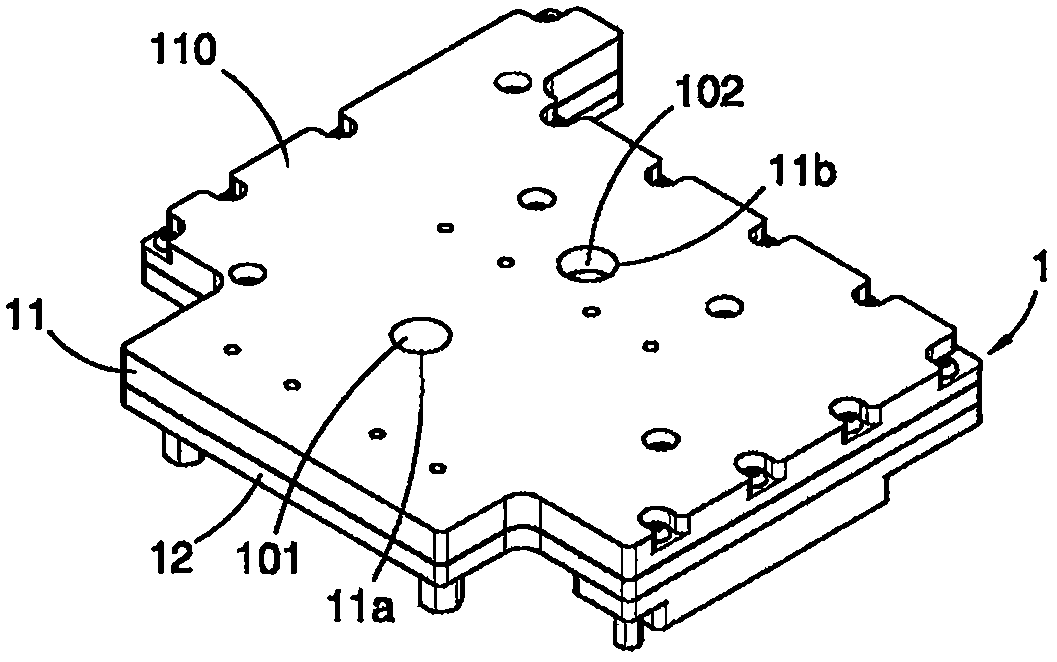
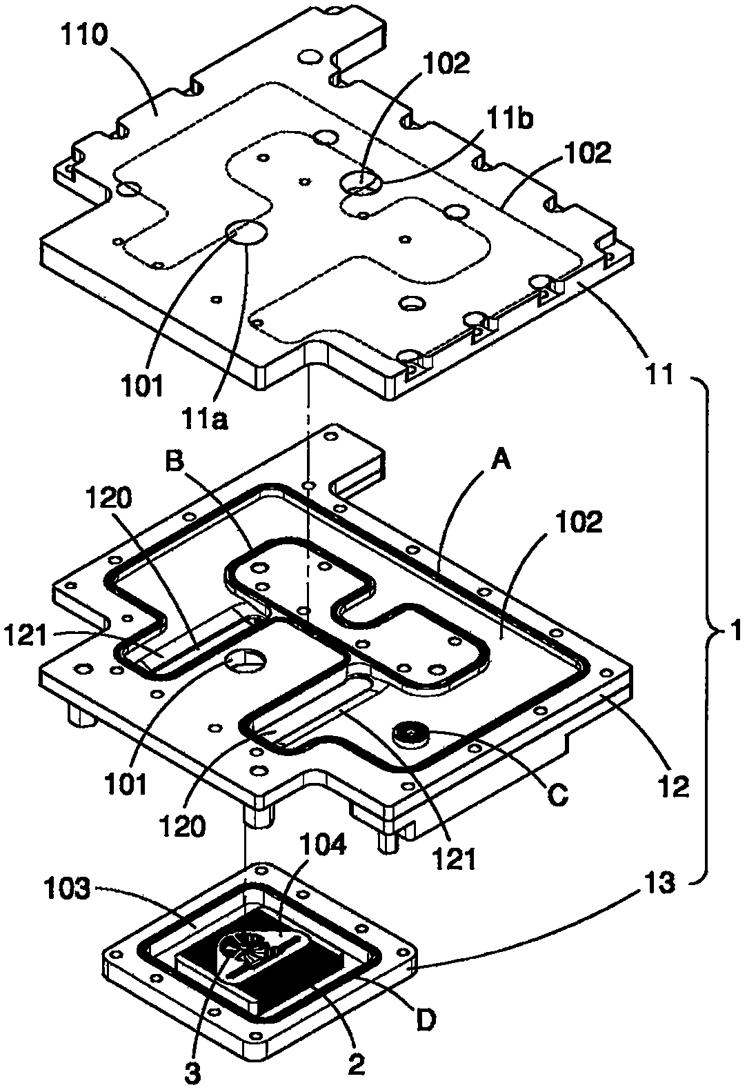
[0072] figure 1 , figure 2 It is a three-dimensional appearance view and a three-dimensional exploded view of a preferred embodiment of the liquid cooling head of the present invention, which includes a heat conduction body 1 , a heat dissipation unit 2 , and a rotating device 3 . The heat-conducting body 1 can be made of heat-conducting metal, such as copper or aluminum, which has an inlet channel 101 for introducing cooling fluid (not shown in the figure), an outlet channel 102 for exporting cooling fluid, and connecting the inlet channel. The channel 101 and a heat exchange area 103 leading out of the flow channel 102 .
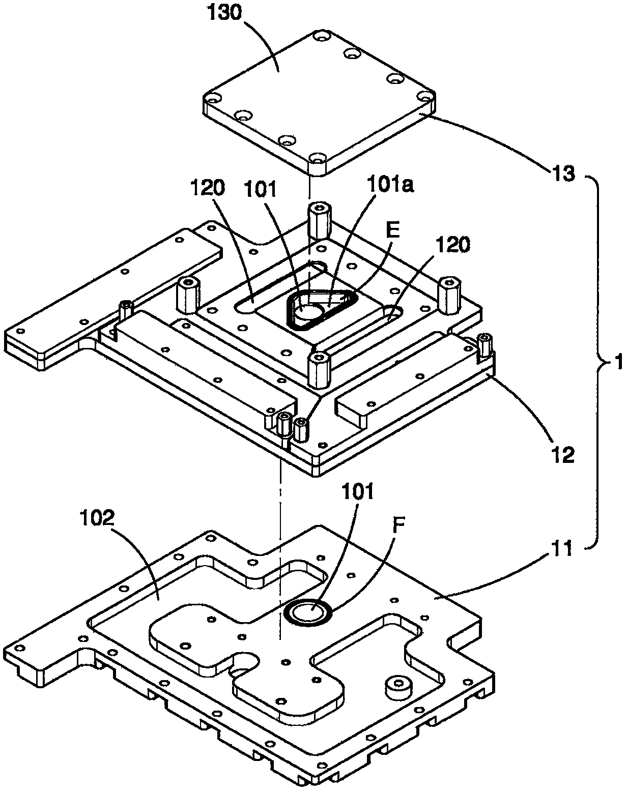
[0073] In this embodiment, for ease of assembly, as figure 2 As shown, the heat conducting body 1 includes a first block 11 , a second block 12 , and a third block 13 stacked in sequence. These blocks 11-13 are closely connected together by a plurality of bolt assemblies (not shown in the figure), and utilize the arrangement of a plurality of sealing ...
PUM
 Abstract
Description
Claims
Application Information