Fuel cell stack

A fuel cell stack and single cell technology, which is applied to fuel cells, fuel cell components, power system fuel cells, etc., can solve problems such as the functional decline of lateral offset of large-scale power generation single cells in fuel cell stacks

Inactive Publication Date: 2020-04-28
HONDA MOTOR CO LTD
View PDF8 Cites 2 Cited by
  • Summary
  • Abstract
  • Description
  • Claims
  • Application Information

AI Technical Summary

Problems solved by technology

However, when the gap is increased, there are problems such as an increase in the size of the fuel cell stack and a decrease in the function of suppressing the lateral displacement of the stacked power generation cells.

Method used


Image

  • Fuel cell stack
  • Fuel cell stack
  • Fuel cell stack

Examples


Embodiment Construction

[0020] Hereinafter, the present invention will be described in detail by citing preferred embodiments with reference to the drawings.

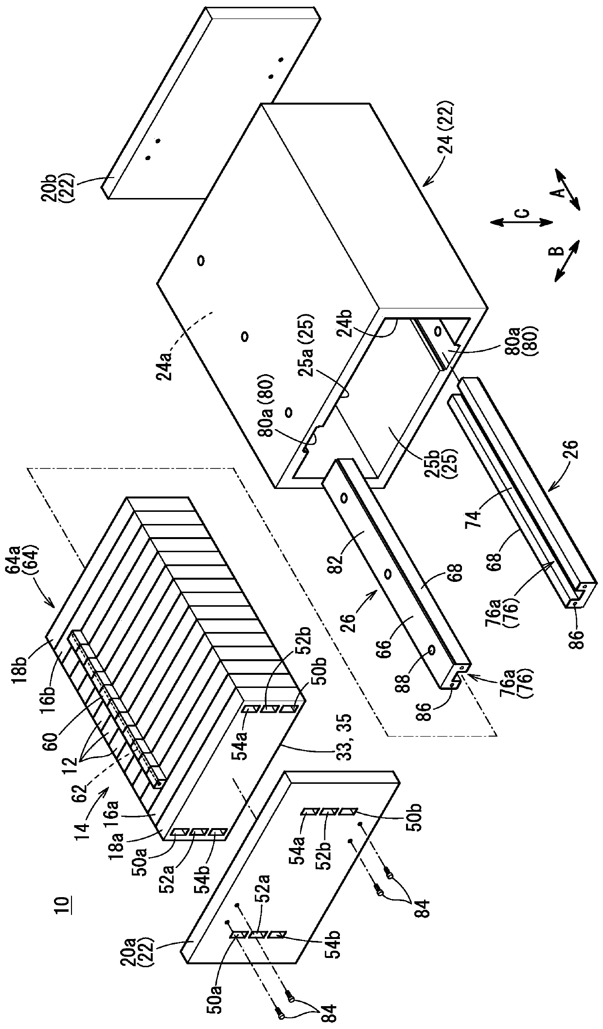
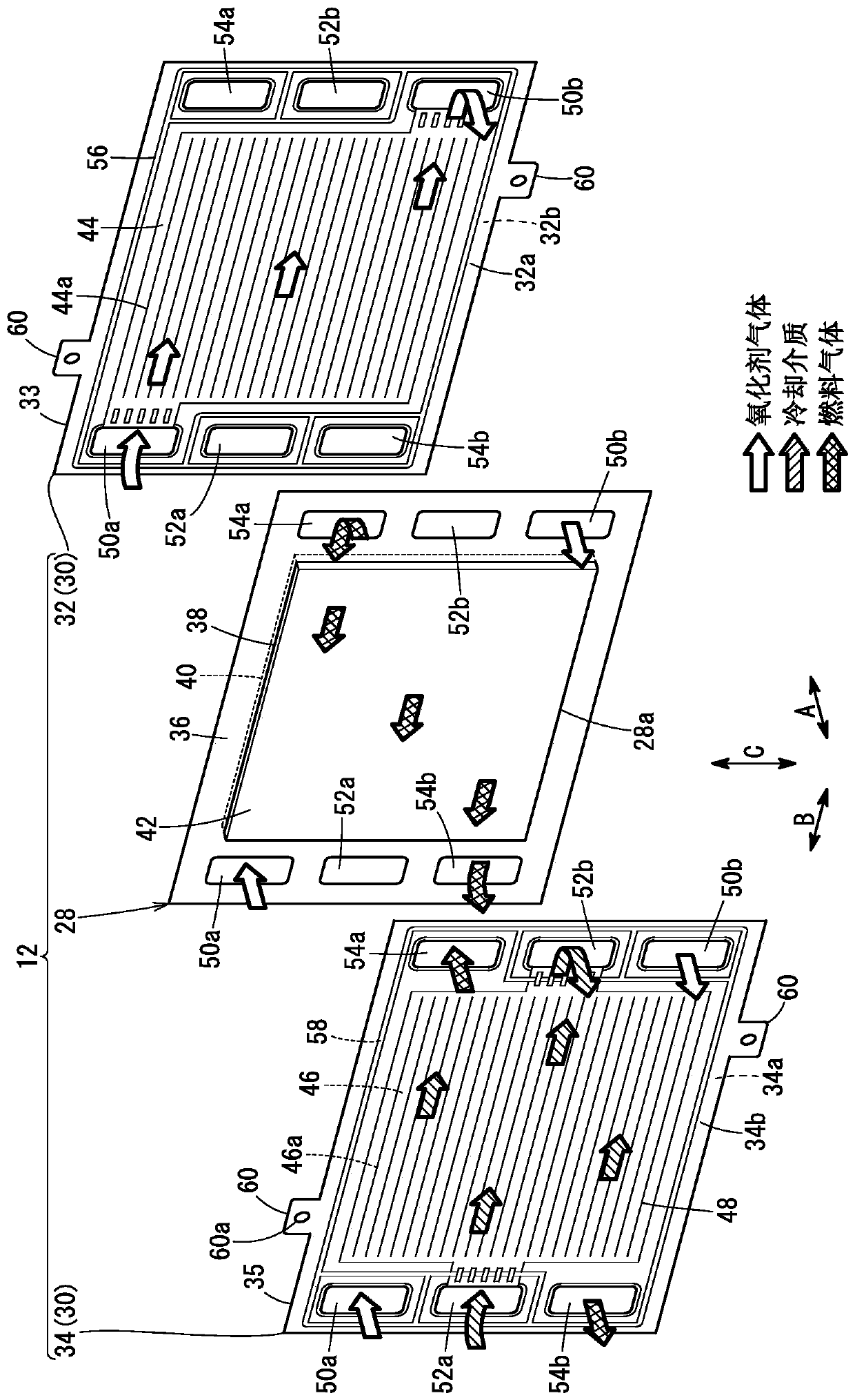
[0021] Such as figure 1 As shown, a fuel cell stack 10 according to an embodiment of the present invention includes a power generating unit cell 12 as a unit fuel cell, and a plurality of power generating unit cells 12 is composed of a stack 14 stacked in the horizontal direction (arrow A direction). . The fuel cell stack 10 is used, for example, mounted on a fuel cell vehicle (not shown). Furthermore, in the state of being mounted on a fuel cell vehicle, the laminated body 14 may be a plurality of power generating cells 12 stacked in the direction of gravity (the direction of the arrow symbol C).

[0022] At one end of the stacked body 14 in the stacking direction (arrow A direction), a terminal plate 16 a and an insulating member 18 a are arranged in this order facing outward. At the other end of the stacked body 14 in the stacking direct...


PUM


Abstract

A fuel cell stack 10 includes a stack body 14 having a plurality of power generation cells 12 that are stacked together, a pair of end plates 20a,20b, a case 22, and a coupling bar 26 provided on a lateral side of the stack body 14, between a pair of end plates 20a,20b for coupling the end plates together. Positioning structure 78 is provided in an inner surface 25 of the case 22 and the couplingbar 26, for defining positions of the inner surface 25 and the coupling bar 26 with respect to each other. The coupling bar 26 includes an engaging part 76 which engages with engaged parts 64 formed in the stack body 14, respectively, and an insulating resin layer 68 provided on a side of the coupling bar including the engaging part closer to the stack body 14.

Description

technical field [0001] The present invention relates to a fuel cell stack in which a plurality of electric generating cells are stacked. Background technique [0002] As disclosed in US Patent Application Publication No. 2016 / 0072145, a fuel cell stack includes a stacked body in which a plurality of power generation cells that generate power using fuel gas and oxidant gas are stacked. Each power generating unit cell has an electrolyte membrane-electrode structure (MEA) in which an anode electrode, an electrolyte membrane, and a cathode electrode are laminated, and a pair of separators that are bipolar plates sandwiching the MEA. [0003] In addition, the separator disclosed in US Patent Application Publication No. 2016 / 0072145 includes a datum protruding outward at a predetermined position on the outer edge. In an assembled state in which the laminate is accommodated in a housing, the adjustment piece is arranged in a recess of the housing. As a result, the fuel cell stack...

Claims


Application Information

Patent Timeline
Patent Type & Authority Applications(China)
IPC IPC(8): H01M8/0202H01M8/2404H01M8/2475
CPCH01M8/0202H01M8/2404H01M8/2475H01M8/241H01M2250/20Y02T90/40Y02E60/50
Inventor 内藤秀晴鹿野嵩瑛
Owner HONDA MOTOR CO LTD
Why Eureka
Try Eureka