Terminal batch assembler for wire harness

A terminal and batch technology, applied in circuit/collector parts, electrical components, circuits, etc., can solve problems such as troublesome and laborious operation, and achieve the effect of easy operation and high work efficiency

Active Publication Date: 2020-04-28
赣州市领沃电子科技有限公司
View PDF6 Cites 0 Cited by
  • Summary
  • Abstract
  • Description
  • Claims
  • Application Information

AI Technical Summary

Problems solved by technology

[0005] In order to overcome the shortcomings of holding the wire harness with one hand, putting the terminal on the end of the wire harness with the other hand, and then pressing the terminal on the wire harness with a tool for assembly, this operation is more troublesome and laborious. Technical problem: provide a Assembling the terminals on the wire harness, the operation is relatively simple, labor-saving, and high-efficiency terminal batch assembler for wire harnesses

Method used


Image

  • Terminal batch assembler for wire harness
  • Terminal batch assembler for wire harness
  • Terminal batch assembler for wire harness

Examples


Embodiment 1

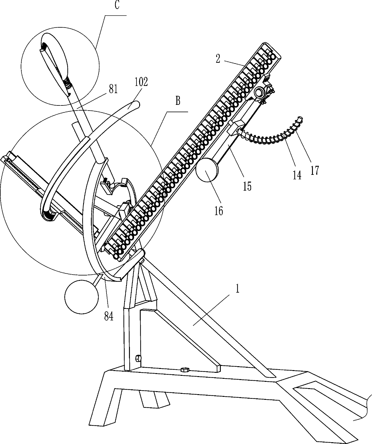
[0022] see figure 1 , figure 2 , image 3 , Figure 4 and Figure 6 , a terminal batch assembler for wire harnesses, including a bracket 1, a placement frame 2, an L-shaped clamping rod 3, a first spring 4, a contact rod 5, a rolling head 6, a second spring 7, a driving mechanism 8 and a blocking mechanism 9. The upper part of the rear side of the bracket 1 is fixedly connected with a placement frame 2 for placing terminals. The bottom of the placement frame 2 is provided with a blocking mechanism 9 that can block the terminals. The L-shaped clamping rod 3, the first spring 4 is wound between the front part of the L-shaped clamping rod 3 and the outer front side of the placement frame 2, and the lower part of the front side of the placement frame 2 is slidingly provided with a contact rod 5, and the contact rod 5 is located at On the right side of the L-shaped clamping rod 3, a second spring 7 is wound between the inner front side of the contact rod 5 and the outer front ...

Embodiment 2

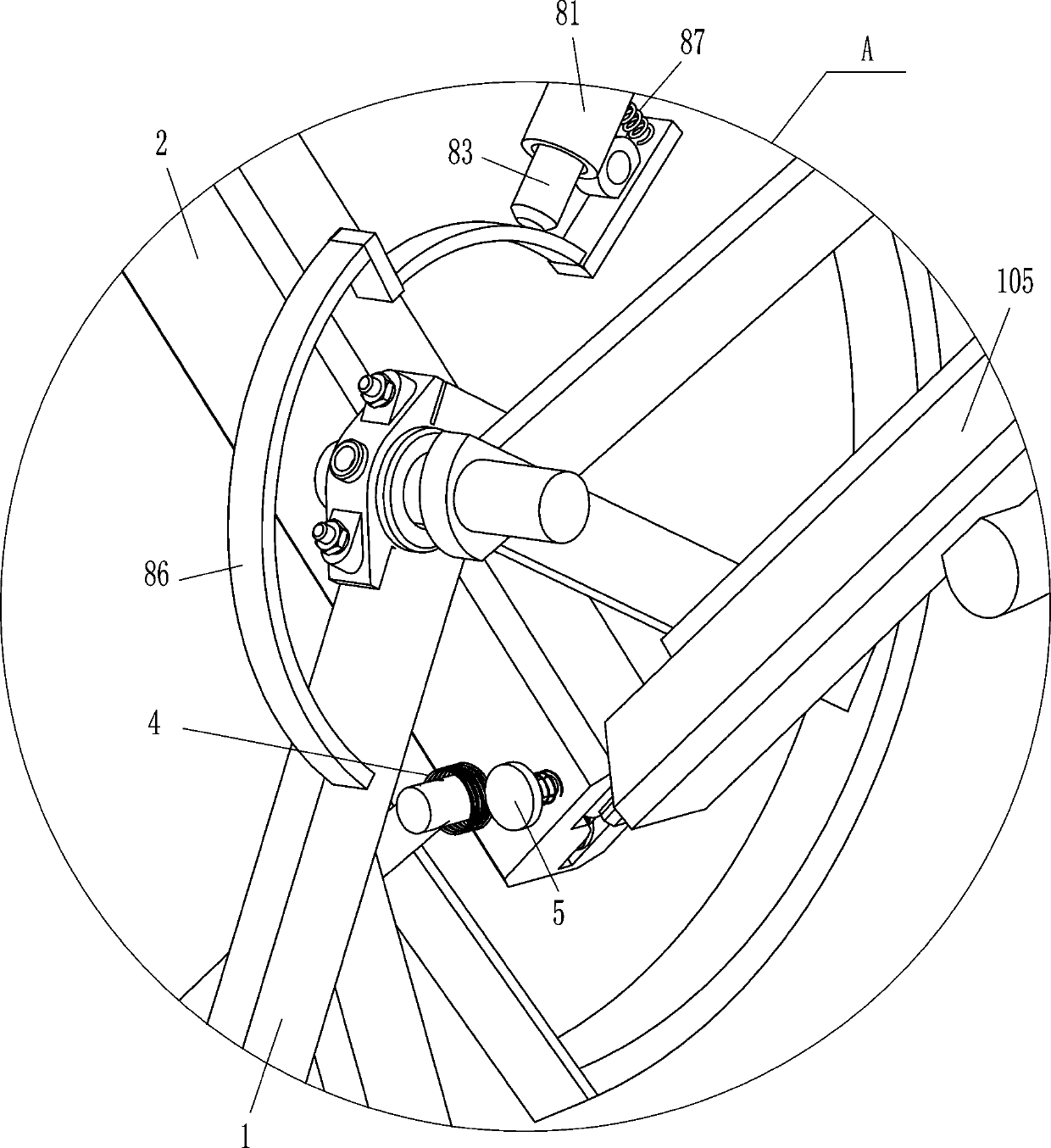
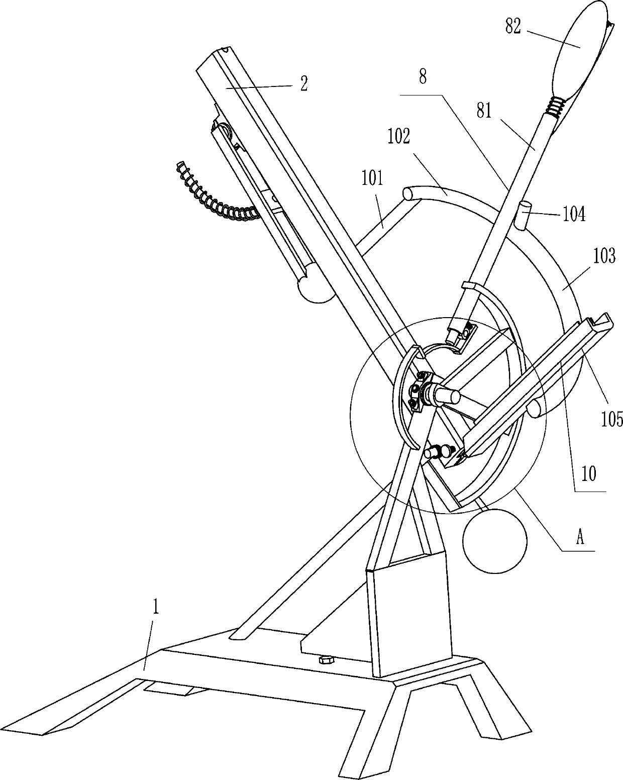
[0029] see figure 1 , figure 2 , Figure 4 and Figure 5 , a terminal batch assembler for wire harnesses. Compared with Embodiment 1, the main difference between this embodiment and this embodiment is that it also includes a placement mechanism 10. The placement mechanism 10 includes a fixed rod 101, an arc rod 102, an arc Sleeve 103, blocking rod 104, frame body 105, sliding frame 106, fifth spring 107 and sixth spring 108, a fixed rod 101 is affixed to the middle of the outer top of the placement frame 2, and an arc rod 102 is affixed to the right end of the fixed rod 101 The lower part of the arc rod 102 is slidingly provided with an arc sleeve 103, a sixth spring 108 is connected between the inner bottom of the arc sleeve 103 and the bottom end of the arc rod 102, and the outer side of the lower part of the arc sleeve 103 is fixedly connected with Frame body 105, the bottom end of frame body 105 is positioned at blocking mechanism 9 right sides, is provided with slidin...

Embodiment 3

[0032] see figure 1 , figure 2 and Figure 6 , a terminal batch assembler for wire harnesses. Compared with Embodiment 1 and Embodiment 2, the main difference of this embodiment is that this embodiment also includes a movable rod 11, a seventh spring 12, an insertion rod 131, and a grip rod 82 The middle part of the rear side is hinged with a movable rod 11, the seventh spring 12 is connected between the upper part of the front side of the movable rod 11 and the inner front side of the grip bar 82, and the lower part of the front side of the movable rod 11 is fixedly connected with an insertion rod 131, and the outer rear side of the hollow cylinder 81 The upper part is provided with a slot 13 for matching with the insertion rod 131 , and the insertion rod 131 is located in the slot 13 .

[0033] Also comprise arc guide rod 14, sliding frame 15, spheroid 16 and the 8th spring 17, place frame 2 outer left side surface top hinged with sliding frame 15, sliding frame 15 bottom...


PUM


Abstract

The invention relates to an assembler, in particular to a terminal batch assembler for wiring harnesses. The technical problem is how to design the terminal batch assembler for the wire harness, whichcan assemble terminals on the wire harness, is simple and convenient to operate, saves labor and is high in working efficiency. The invention discloses the terminal batch assembler for the wire harness. The terminal batch assembler comprises a bracket, a placing frame, an L-shaped clamping rod, a first spring, a contact rod, a rolling head and the like, wherein an upper part of a rear side of thebracket is fixedly connected with the placing frame for placing terminals, a bottom end of the placing frame is provided with a blocking mechanism for blocking the terminals, and a lower part of a front side of the placing frame is slidably provided with the L-shaped clamping rod for fixing the terminals. A proper amount of terminals are placed in the placing frame, one end of the wire harness isinserted into the terminals, a holding rod is pulled to rotate reversely to enable the rolling head to move backwards to press the terminals on the wire harness for assembly, a person does not need to hold the wire harness with one hand and sleeve the terminal on an end of the wire harness with the other hand to press and assemble with a tool, the operation is easy and convenient, the labor is saved, and the work efficiency is high.

Description

technical field [0001] The invention relates to an assembler, in particular to a terminal batch assembler for wire harnesses. Background technique [0002] The terminal is the part where the battery is connected to the external conductor. In electrical engineering, terminals refer to terminal terminals, also known as terminal blocks. The types are divided into single holes, double holes, sockets, hooks, etc., and the materials are divided into silver-plated copper, galvanized copper, copper, aluminum, iron, etc. Their function is mainly to transmit electrical signals or conduct electricity. Before the wire harness is used, it is necessary to assemble the terminals on the end of the wire harness so that the wire harness can be used in the next step. [0003] At present, people hold the wire harness with one hand, put the terminal on the end of the wire harness with the other hand, and then use tools to press the terminal on the wire harness for assembly. This operation is tr...

Claims


Application Information

Patent Timeline
IPC IPC(8): H01R43/048
CPCH01R43/048
Inventor 许远贵
Owner 赣州市领沃电子科技有限公司
Why Eureka
Try Eureka