
Motor auxiliary device paying attention to heat dissipation

A technology for auxiliary devices and heat dissipation mechanisms, applied in the direction of electromechanical devices, circuit devices, emergency protection circuit devices, etc., can solve problems that affect work performance, reduce motor life, increase costs, etc., to improve heat dissipation efficiency and quality, ensure efficiency, The effect of energy saving

Active Publication Date: 2020-04-28
浙江贤丰机电设备有限公司
View PDF5 Cites 4 Cited by
  • Summary
  • Abstract
  • Description
  • Claims
  • Application Information

AI Technical Summary

Problems solved by technology

During the operation of the motor, the heat generated continues to accumulate with the increase of time, which makes the temperature inside the motor gradually rise, which affects the performance of the internal parts of the motor and has a great impact on the service life of each part. Existing The cooling device of the motor is usually only for long-term air cooling, which not only consumes a lot of energy and makes a lot of noise, but also when the motor is overloaded and cut off, it will often stop working together. On the contrary, the motor that is overheated due to overload will stop cooling, reducing The life of the motor, and the existing motor auxiliary devices often use fuses for overload protection, that is, what we often call fuses. When the overload is removed for such devices, the fuses often need to be replaced to allow the motor to continue to operate, which not only increases the cost and waste manpower

Method used


Image

  • Motor auxiliary device paying attention to heat dissipation
  • Motor auxiliary device paying attention to heat dissipation
  • Motor auxiliary device paying attention to heat dissipation

Examples


Embodiment Construction

[0020] Combine below Figure 1-7 The present invention is described in detail, and for convenience of description, the orientations mentioned below are now stipulated as follows: figure 1 The up, down, left, right, front and back directions of the projection relationship itself are the same.

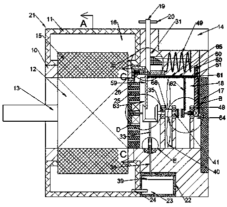
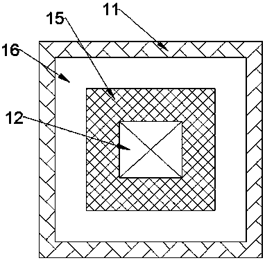
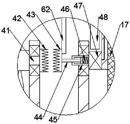
[0021] 1. Reference Figure 1-7According to an embodiment of the present invention, a motor auxiliary device focusing on heat dissipation includes a body 10, a motor 12 is provided inside the body 10, and a rotatable output shaft 13 is fixed on the outer surface of the left end of the motor 12, The output shaft 13 extends to the outside, the left end of the fuselage 10 is provided with a water-cooled heat dissipation mechanism 21 for preliminary heat dissipation of the motor 12 in operation, and the outer surface of the right end of the motor 12 is fixed with a ventilation partition 25, The right side of the ventilation partition 25 is provided with a cooling chamber 18, and the ventil...


PUM


Abstract

The invention discloses a motor auxiliary device paying attention to heat dissipation. The device comprises a machine body, a motor is arranged in the machine body; a rotatable output shaft is fixedlyarranged on an outer surface of a left end of the motor and extends to the outside, a water-cooled heat dissipation mechanism for conducting preliminary heat dissipation on the motor in operation isarranged at a left end of the machine body, a ventilation partition plate is fixedly arranged on an outer surface of a right end of the motor, and a heat dissipation cavity is formed in a right side of the ventilation partition plate. Overload protection can be carried out on the motor, meanwhile, after overload protection, an independent power supply is switched for a fan, the heat dissipation iscarried out on the motor which is overheated due to overload, meanwhile, after overload reasons are eliminated, an inclined rod can be manually pulled out to enable the power supply to be connected with the motor again, the motor is powered on, the cost is saved, and meanwhile, the operation is easier.

Description

technical field [0001] The invention relates to the technical field of motors, in particular to a motor auxiliary device focusing on heat dissipation. Background technique [0002] Motors are widely used in electronics and automation equipment industries. During the operation of the motor, the heat generated continues to accumulate with the increase of time, which makes the temperature inside the motor gradually rise, which affects the performance of the internal parts of the motor and has a great impact on the service life of each part. Existing The cooling device of the motor is usually only for long-term air cooling, which not only consumes a lot of energy and makes a lot of noise, but also when the motor is overloaded and cut off, it will often stop working together. On the contrary, the motor that is overheated due to overload will stop cooling, reducing The life of the motor, and the existing motor auxiliary devices often use fuses for overload protection, that is, wh...

Claims


Application Information

Patent Timeline
Patent Type & Authority Applications(China)
IPC IPC(8): H02K9/19H02K5/20H02K9/04H02K11/20H02K9/22H02H7/085H02H3/06
CPCH02H3/06H02H7/085H02K5/20H02K9/04H02K9/19H02K9/22H02K11/20
Inventor 不公告发明人
Owner 浙江贤丰机电设备有限公司
Learn More