Traction converter circuit

A traction converter and circuit technology, applied in the direction of AC motor control, AC power input conversion to AC power output, electrical components, etc., can solve the problem of increasing the number of traction transformers used for power supply, and the large volume and weight of traction converter equipment , affecting the normal operation of locomotives, etc., to achieve the effect of improving availability and reliability, reducing volume and weight, and avoiding coupling effects

Inactive Publication Date: 2020-04-28
ZHUZHOU CSR TIMES ELECTRIC CO LTD
View PDF6 Cites 8 Cited by
  • Summary
  • Abstract
  • Description
  • Claims
  • Application Information

AI Technical Summary

Problems solved by technology

In the existing locomotive traction converters, the structure of multiple main converter circuits sharing the intermediate DC circuit is adopted, so that the mutual coupling effects between the main converter circuits, once the power module in a certain main converter circuit fails, the Power modules in other main converter circuits need to be blocked as well, reducing availability and affecting the normal operation of the locomotive
Moreover, the main and auxiliary separation structure is generally adopted in the prior art, that is, the auxiliary converter circuit and the main converter circuit are powered separately, which undoubtedly increases the number of traction transformers used for power supply, and makes the entire traction converter equipment Bigger in size and weight

Method used


Image

  • Traction converter circuit
  • Traction converter circuit
  • Traction converter circuit

Examples


Embodiment Construction

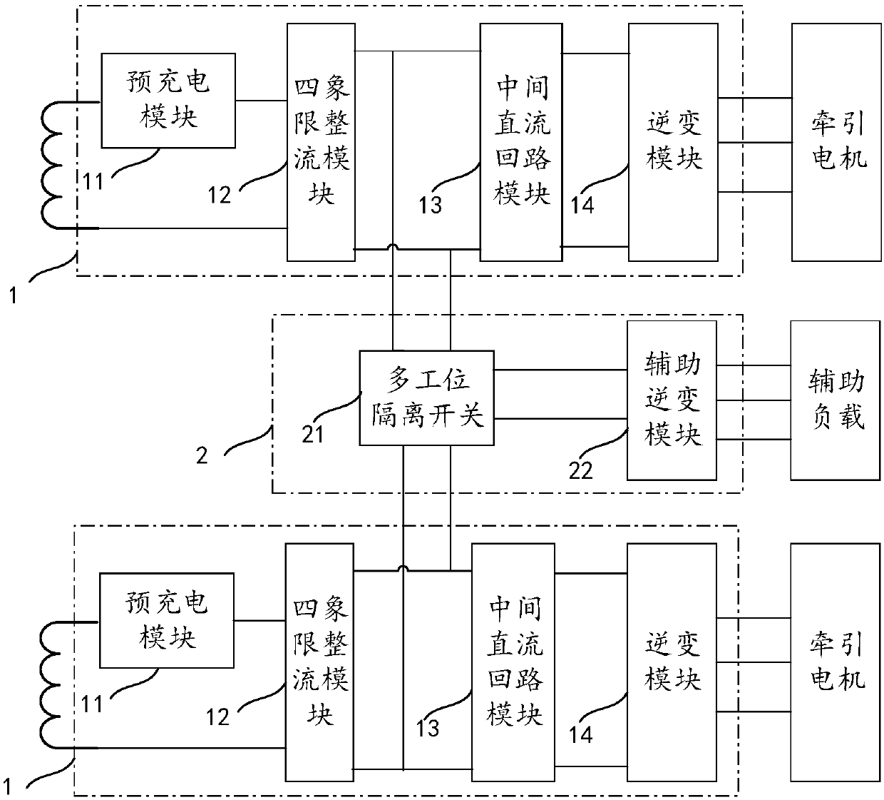
[0028] The core of the present application is to provide a traction converter circuit, so as to effectively improve the availability and reliability of the traction converter, and reduce the volume and weight of the equipment.

[0029] In order to describe the technical solutions in the embodiments of the present application more clearly and completely, the technical solutions in the embodiments of the present application will be introduced below in conjunction with the drawings in the embodiments of the present application. Apparently, the described embodiments are only some of the embodiments of this application, not all of them. Based on the embodiments in this application, all other embodiments obtained by persons of ordinary skill in the art without making creative efforts belong to the scope of protection of this application.

[0030] Please refer to figure 1 , figure 1 A structural block diagram of a traction converter circuit provided by this application, mainly incl...


PUM


Abstract

The invention discloses a traction converter circuit. The traction converter circuit comprises an auxiliary conversion loop and multiple completely independent main conversion loops; each main conversion loop comprises a pre-charging module, a four-quadrant rectification module, an intermediate direct-current loop and an inversion module which are connected in sequence, wherein the pre-charging module is used for performing on-off control on the pre-charging process and normal working process of the traction converter circuit, the four-quadrant rectification module sets input alternating current into direct current and inputs the direct current into the intermediate direct-current loop, and the intermediate direct-current loop comprises a support capacitor for voltage stabilization; and the auxiliary conversion loop comprises a multi-station isolation switch and an auxiliary inversion module which are connected with each other, wherein the multi-station isolation switch is in switchingconnection with the intermediate direct-current loop of any main current conversion loop so as to take electricity for the auxiliary inversion module. According to the traction converter, a full-independent shaft control type and main and auxiliary integrated structure is adopted, the usability and reliability of the traction converter are effectively improved, and the size and weight of equipment are reduced.

Description

technical field [0001] The present application relates to the technical field of locomotive traction transmission, in particular to a traction converter circuit. Background technique [0002] With the steady growth of the national economy, my country's transportation industry, especially rail transportation, is also booming and busier. [0003] The traction converter is the core component of the locomotive transmission system, and its performance has a huge impact on the operating efficiency. Through the traction converter circuit, the electric energy of the power supply can be rectified and inverted successively to generate alternating current of appropriate frequency and size for use by the locomotive. Generally, the traction converter circuit in a locomotive includes a main converter circuit for supplying power to the traction motor and an auxiliary converter circuit for supplying power to auxiliary loads and the like. In the existing locomotive traction converters, the...

Claims


Application Information

Patent Timeline
Patent Type & Authority Applications(China)
IPC IPC(8): H02M5/458H02P27/06
CPCH02M5/458H02P27/06
Inventor 王雨张义饶艺伟李学明梁兴元刘毅陈志博范荣辉范斌陈侃冯秋实
Owner ZHUZHOU CSR TIMES ELECTRIC CO LTD
Why Eureka
Try Eureka