
A method and system for generating SPWM wave by using FPGA

A technology for generating modules and sine waves, which is applied in the direction of output power conversion devices, electrical components, single-network parallel feeding arrangements, etc., and can solve problems such as obvious hysteresis effect, insufficient response, and tediousness

Active Publication Date: 2021-01-01
HUBEI UNIV FOR NATITIES
View PDF5 Cites 0 Cited by
  • Summary
  • Abstract
  • Description
  • Claims
  • Application Information

AI Technical Summary

Problems solved by technology

However, the generation of its SPWM wave often requires some special DSP chips, which are usually used in some occasions that require very high waveform indicators. This basic SPWM control technology cannot meet the impact on the output waveform after the load changes, and currently on the market It is often cumbersome to realize the function of controlling the photovoltaic inverter to convert the DC power into a sine wave AC current with the same frequency and phase as the grid and connect it to the grid to realize grid-connected power generation, and the response is not fast enough, and the hysteresis effect is very obvious

Method used


Image

  • A method and system for generating SPWM wave by using FPGA
  • A method and system for generating SPWM wave by using FPGA
  • A method and system for generating SPWM wave by using FPGA

Examples


Embodiment 1

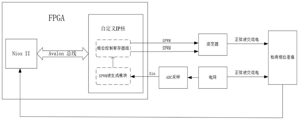
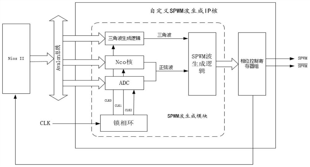
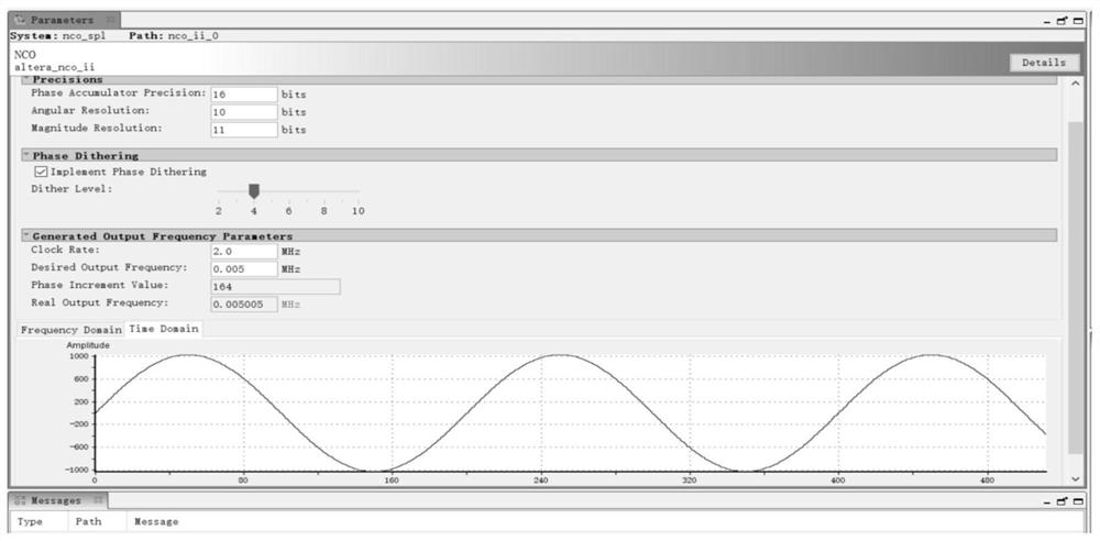
[0043] Such as figure 1 Shown in the overall framework of the system, the self-defining IP core of the present invention is a kind of IP core with Avalon bus, which can be easily attached to the NiosII processor, allowing the NiosII soft core to control the self-defining IP core through the Avalon bus, so that the The IP core generates the required SPWM waves according to user requirements. The core part of the FPGA system is the self-defined SPWM wave generation IP core, which is also the key point of this patent. The IP core is mainly composed of initial control register, sine wave selection register group, SPWM wave generation logic module, phase control register group module, and Avalon read and write control logic module. It can output high-precision, easy-to-real-time control, and phase-adjustable SPWM waves. The initial control register is used to control whether the IP core starts working and stops working; this IP core contains two methods for generating sine waves. ...

Embodiment 2

[0079] This embodiment takes the control of a three-phase inverter circuit inverter grid connection as an example to explain the specific design scheme and parameters of the IP core proposed by this patent, so first we use the Nios II processor to control the IP core to use the external high-speed parallel ADC pair The peripheral circuit samples the power grid to obtain a sine wave signal. It is assumed here that we can set a clock clk0 with a frequency of 1M Hz for the triangular wave generation module to generate a triangular wave with a frequency of 10K Hz, and then set a clock clk2 with a frequency of 10K Hz for high-speed parallel ADC to sample the sine wave on the power grid, specifically How to determine the clock frequency has been mentioned above, and will not be described in detail here. The system samples the specific AC circuit through the ADC module to obtain SIN1, SIN2 and SIN3, and needs to use the IP core designed by this patent to generate corresponding SPWM w...


PUM


Abstract

The invention discloses a method and system for generating SPWM waves by using FPGA, including an external ADC sampling module and a self-defined IP core. The self-defined IP core includes an SPWM wave generation module and a phase control register group. The SPWM wave generation module Including triangular wave generation module, sine wave generation module, phase-locked loop and SPWM wave generation logic module. The system customizes the Avalon bus interface equipped with the IP core, so that the selection of the sine wave and the phase of the generated signal can be conveniently set by the CPU by accessing the register. The IP core designed by this scheme has the advantages of high precision, easy to use, good SPWM waveform generated, and less resource occupation. The entire process independently generates SPWM waves and releases the processor.

Description

technical field [0001] The invention relates to the technical field of power electronics, in particular to a method and system for generating SPWM waves by using FPGA. Background technique [0002] With the depletion of fossil energy such as coal and oil and the continuous deterioration of the human living environment, the development and utilization of renewable natural resources such as solar energy and wind energy have received widespread attention at home and abroad in recent years, and many countries have made large-scale promotion of renewable energy such as solar energy. Decision-making and planning for the development and utilization of renewable energy. For the current new energy power generation, the disadvantages of poor stability, difficulty in continuous operation, and large environmental factors still restrict its development to a certain extent. Therefore, it is imperative to find a reliable and efficient energy conversion method. Since the inverter can conve...

Claims


Application Information

Patent Timeline
Patent Type & Authority Patents(China)
IPC IPC(8): H02M7/529H02M7/521H02J3/38
CPCH02M7/521H02M7/529H02M1/0012
Inventor 刘三军宋鹏龙来国红谭建军孙先波朱黎李绍武高仕红徐建胡俊鹏
Owner HUBEI UNIV FOR NATITIES
Learn More