A new type of mobile device antenna

A mobile device and antenna technology, which is applied in the field of new mobile device antennas, can solve problems such as unsatisfactory usage conditions, and achieve the effects of small footprint, high antenna gain, and low cost

Active Publication Date: 2020-03-27
ZHEJIANG UNIV
View PDF7 Cites 0 Cited by
  • Summary
  • Abstract
  • Description
  • Claims
  • Application Information

AI Technical Summary

Problems solved by technology

However, due to the diversity of radio frequency communication circuit systems, most of the use cases cannot be met, so it is necessary to design a new mobile device antenna to meet the needs

Method used


Image

  • A new type of mobile device antenna
  • A new type of mobile device antenna
  • A new type of mobile device antenna

Examples


Embodiment Construction

[0018] The present invention will be further described below in conjunction with the accompanying drawings and specific embodiments.

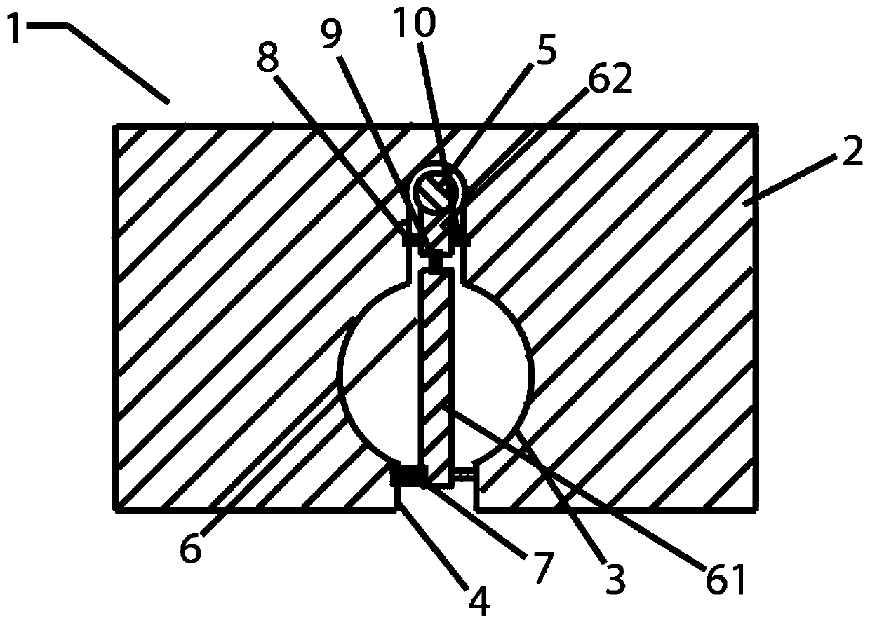
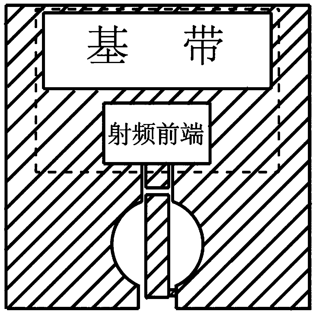
[0019] Such as figure 1 and figure 2 As shown, the mobile device antenna 1 specifically implemented includes a PCB circuit copper-clad laminate 2, a microstrip line 6 and a capacitance matching circuit. There is a notch on the PCB circuit copper-clad laminate 2, and the notch is mainly composed of a circular notch 3 and a rectangular gap 4. , the circular gap 3 extends to the edge of the PCB circuit copper clad laminate 2 through the rectangular gap 4; a microstrip line 6 is arranged in the circular gap 3 of the gap groove, and the microstrip line 6 is connected to the PCB circuit copper clad laminate 2 through the capacitance matching circuit; the gap The slot is connected to the RF transceiver front end via a microstrip with matching capacitors.

[0020] The microstrip line 6 is mainly composed of a lower conductor strip 61, an upper condu...


PUM


Abstract

The invention discloses a novel mobile equipment antenna. The novel mobile equipment antenna comprises a PCB copper-coated plate and a gap groove, wherein the gap groove is formed in one side of the copper-coated plate, a microstrip line is arranged at the middle part of the gap groove and is connected with an internal circuit of the PCB copper-coated plate, the microstrip line on the gap groove are simultaneously connected with a plurality of capacitors to be used a matching circuit, one end of the microstrip line is connected with a radio frequency emission front end via the matching circuit, the other end of the microstrip line is connected with an edge of a PCB via a zero-crossing ohmic resistor, and the antenna working frequency and the circuit matching effect can be flexibly adjustedby changing a parameter of a matching capacitor on the gap groove. The employed antenna can be used for connecting various radio frequency communication chips, and radiation is performed through a metal edge outside the PCB by the gap groove of the PCB; the antenna can be introduced into various types of miniature communication equipment, the area occupied by separately designing the antenna is reduced, and meanwhile, relatively high radiation efficiency and relatively good omnidirectivity are maintained; and the antenna is simple in design structure, low in cost and adjustable in design parameter and can be widely applied to an application occasion such as an internet of things terminal.

Description

technical field [0001] The invention relates to an antenna, in particular to a novel mobile device antenna. Background technique [0002] In wireless communication technology, radio frequency transceiver front-end circuits and systems are becoming more and more highly integrated, and very miniaturized wireless application systems can be designed. Among them, the miniaturization of the antenna also puts forward higher and higher size and index requirements. However, the antenna design of the existing mobile terminal must meet a certain size requirement, so that the electromagnetic wave can effectively radiate and receive the electromagnetic wave signal within the scale of one working wavelength to one quarter wavelength of the working frequency. At the same time, in order to avoid mutual interference between the antenna and other circuit structures, the antenna itself needs to occupy a certain space in the circuit system, which affects the volume and size of the wireless cir...

Claims


Application Information

Patent Timeline
Patent Type & Authority Patents(China)
IPC IPC(8): H01Q1/36H01Q1/38H01Q1/50H01Q5/10H01Q5/335H01Q5/50
CPCH01Q1/36H01Q1/38H01Q1/50H01Q5/10H01Q5/335H01Q5/50
Inventor 皇甫江涛汤之仪
Owner ZHEJIANG UNIV
Why Eureka
Try Eureka