Construction method of annular cable-supported grid structure with upper grid participating in balancing inhaul cable pretension

A kind of cable pre-tension and grid structure technology, applied in building construction, building material processing, construction and other directions, can solve the problems of high cost of tire frame measures, unfavorable loop cable spreading and lifting and installation, etc., and achieve high efficiency. And high-precision construction molding, reducing the effect of structural deformation

Inactive Publication Date: 2020-05-01
SOUTHEAST UNIV
View PDF7 Cites 0 Cited by
  • Summary
  • Abstract
  • Description
  • Claims
  • Application Information

AI Technical Summary

Problems solved by technology

In large-scale stadium projects, due to the large overhang of the upper grid, it is often necessary to set tire frames separately under the main grid and the overhang grid, and the cost of tire frame measures is high; and the hoops are often located between the two tire frames. This is very unfavorable for the spreading and lifting installation of the ring cable; in addition, in order to avoid the downward deflection of the cantilever grid, the support under the cantilever grid needs to be installed after the tensioning of the cables, and the upper deflection of the cantilever grid must also be detached through the top support shelf

Method used


Image

  • Construction method of annular cable-supported grid structure with upper grid participating in balancing inhaul cable pretension
  • Construction method of annular cable-supported grid structure with upper grid participating in balancing inhaul cable pretension
  • Construction method of annular cable-supported grid structure with upper grid participating in balancing inhaul cable pretension

Examples


Embodiment

[0027] Embodiment: A construction method of a ring-shaped cable-supported grid structure in which the upper grid participates in balancing the pretension of the cables, and the method includes the following steps:

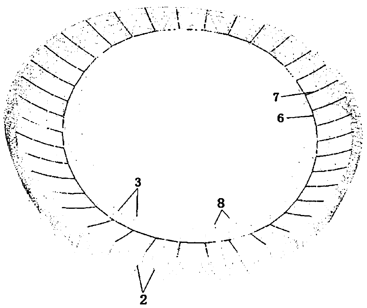
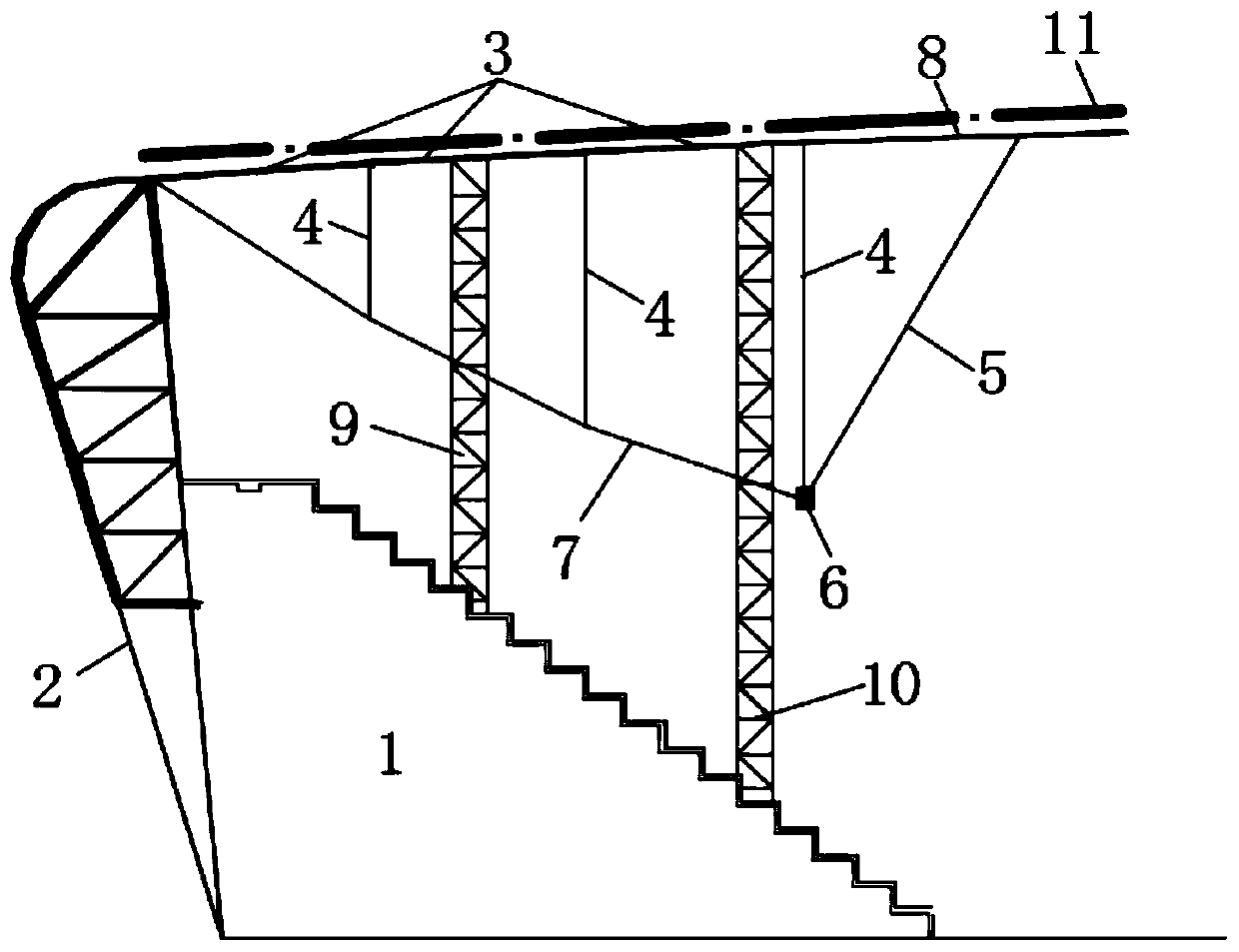
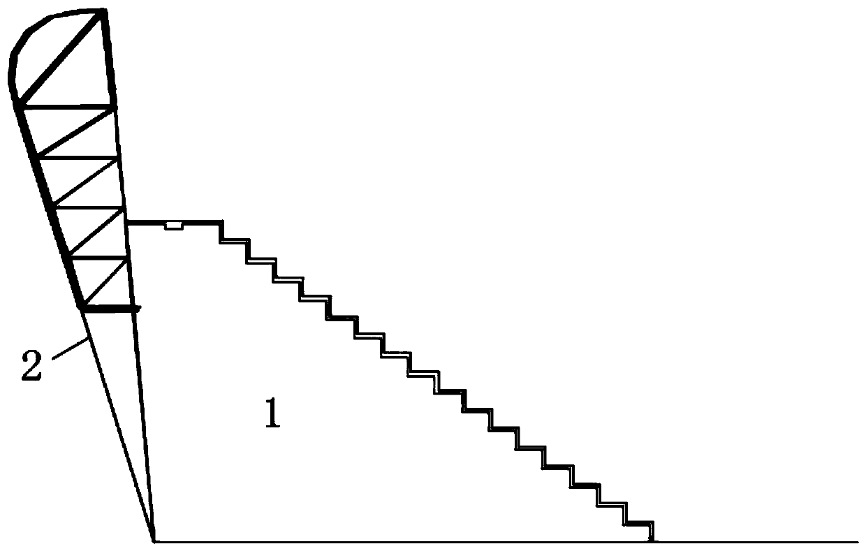
[0028] Step 1: Install the pillars and outer ring;

[0029] Step 2: Install the tire frame, that is, install the tire frame under the main grid that can be both compressed and tensioned, and a horizontal sliding device is installed on the top of the tire frame; the horizontal displacement of the upper grid is not restricted;

[0030] Step 3: Install the main grid and corresponding struts on the tire frame, and the tire frame is under pressure at this time;

[0031] Step 4: Install and tension the lower cable net. At this time, the tire frame is under tension and there is a horizontal relative slippage between the top and the main grid;

[0032] Step 5: Install the cantilever grid and corresponding struts;

[0033] Step 6: Remove the tire frame after installing pa...


PUM


Abstract

The invention discloses a construction method of an annular cable-supported grid structure with an upper grid participating in balancing inhaul cable pretension. The construction method comprises thefollowing construction steps of (1) mounting a column and an outer ring; (2) installing a jig frame capable of being pressed and pulled below a main grid, and arranging a horizontal sliding device onthe top of the jig frame; (3) mounting the main grid and corresponding supporting rods on the jig frame, wherein the jig frame is pressed at the moment; (4) mounting and tensioning a lower cable net,wherein the jig frame is pulled, and the top end of the jig frame horizontally slides relative to the main grid; (5) mounting cantilever grids and corresponding supporting rods; and (6) finally dismounting the jig frame after mounting a part or all of a roof system. According to the construction method, the jig frame does not need to be arranged below the overhanging grids, and ring cable spreading and lifting installation are facilitated; the jig frame capable of being pressed and pulled is arranged to maintain the elevation of the main grid when an inhaul cable is tensioned, and the mountingprecision of the cantilever grids is controlled; and the construction method conforms to the mechanical property of the cable-supported grid structure with the upper grid participating in balancing inhaul cable pretension, and efficient and high-precision construction forming is facilitated.

Description

technical field [0001] The invention relates to a construction method, in particular to a construction method of an annular cable-supported grid structure in which the upper grid participates in balancing the pretension force of the cables, and belongs to the technical field of large-span space cable structures. Background technique [0002] In large-span space buildings, the ring-shaped cable-supported grid structure is generally composed of columns, outer rings, upper grids, lower cable nets and struts. The upper grid includes main grids and overhang grids, and the lower cable nets Radial cables and circular cables. The outer ring is located at the top of the column; the outer edge of the upper grid and the outer end of the radial cable are connected to the outer ring; the inner end of the radial cable is connected to the hoop cable; the upper end of the strut is connected to the upper grid, and the strut The lower end is connected with the radial cable and the hoop cable...

Claims


Application Information

Patent Timeline
Patent Type & Authority Applications(China)
IPC IPC(8): E04B1/342E04G21/00
CPCE04B1/342E04G21/00
Inventor 罗斌张旻权刘海霞阮杨捷
Owner SOUTHEAST UNIV
Why Eureka
Try Eureka