Self-balancing multi-stage pump four-volute-chamber water outlet structure

A water discharge structure and multi-stage pump technology, applied in the field of multi-stage pumps, can solve the problems of large water discharge resistance, poor rigidity of the main shaft, and reduced service life, and achieve the effects of shortening the length of the main shaft, increasing the rigidity of the rotor, and improving the reliability

Pending Publication Date: 2021-10-19
CHANGSHA CANON GENERAL PUMPS
View PDF7 Cites 0 Cited by
  • Summary
  • Abstract
  • Description
  • Claims
  • Application Information

AI Technical Summary

Problems solved by technology

[0003] Existing multi-stage pumps are mostly self-balancing multi-stage pumps and balanced disc multi-stage pumps, which have a long discharge stage, poor rigidity of the main shaft, and low reliability
The vortex chambers of existing multi-stage pumps are all spiral or circular. When the high-lift and large-flow water flow is thrown out of the spiral vortex chamber, there are problems such as large water outlet resistance, uneven flow, large noise, and serious cavitation
The shape of the existing vortex chamber and the design of the water outlet angle do not fully conform to the principle of fluid mechanics, and it cannot ensure that the water flow enters the outlet pipe very uniformly. Greater wear, greater noise, greater cavitation
In addition, the shape of the pump tongue of the existing multi-stage pump is simple triangle, inclined plane or arc shape, which does not match the hydraulic action. pump life

Method used


Image

  • Self-balancing multi-stage pump four-volute-chamber water outlet structure
  • Self-balancing multi-stage pump four-volute-chamber water outlet structure
  • Self-balancing multi-stage pump four-volute-chamber water outlet structure

Examples


Embodiment Construction

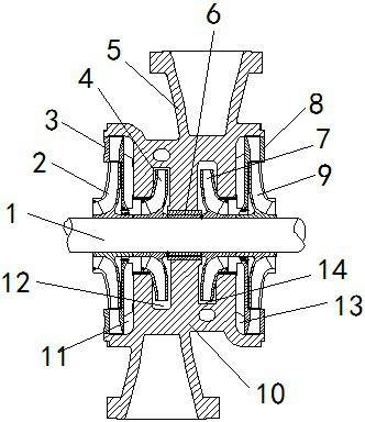
[0031]The present invention will be further described below in combination with specific embodiments. Wherein, the accompanying drawings are only for illustrative purposes, showing only schematic diagrams, rather than physical drawings, and should not be construed as limitations on this patent; in order to better illustrate the embodiments of the present invention, some parts of the accompanying drawings will be omitted, Enlargement or reduction does not represent the size of the actual product; the descriptions of the positions of the front, middle, rear, upper, middle, lower, left and right, sides, ends, head, etc. in the embodiments are only for convenience of illustration and cannot be understood as a description of the present invention. For constraints and limitations of actual locations, it is understandable to those skilled in the art that certain known structures and technical descriptions in the embodiments may be omitted.

[0032] like figure 1 As shown, the presen...


PUM


Abstract

The invention relates to a self-balancing multi-stage pump four-volute-chamber water outlet structure. The self-balancing multi-stage pump four-volute-chamber water outlet structure comprises a pump body; a main shaft is arranged in the center of the pump body; a positive impeller and a final-stage positive impeller are installed on the left side of the main shaft; a negative impeller and a final-stage negative impeller are installed on the right side of the main shaft; a water outlet section is arranged in the middle of the pump body and provided with four volute chambers; the positive impeller and the final-stage positive impeller are symmetrically arranged in the two volute chambers on the left side of the water outlet section; the final-stage negative impeller and the negative impeller are symmetrically arranged in the two volute chambers on the right side of the water outlet section; a positive guide vane is installed on the left side of the water outlet section; a negative guide vane is installed on the right side of the water outlet section; the first volute chamber and the third volute chamber are both round volute chambers; the second volute chamber is a spiral volute chamber; and the fourth volute chamber is a spiral parabolic volute chamber. Through the unique structural design, the efficiency of a pump is improved, noise is lowered, and the service life of the pump is prolonged.

Description

technical field [0001] The invention relates to the technical field of multistage pumps, in particular to a water outlet structure of a self-balancing multistage pump with four vortex chambers. Background technique [0002] Self-balancing multi-stage centrifugal pumps are composed of stator parts and rotor parts. Among them, the stator parts are composed of water inlet section, middle section, positive guide vane, reverse guide vane, water outlet section, secondary water inlet section, front and rear bearing bodies, transition The rotor components are composed of the main shaft, the positive impeller, the reverse impeller, the shaft sleeve, the bearing retainer sleeve, the middle and rear throttling sleeves, and the coupling. The prime mover drives the water pump to rotate, the medium is sucked in from the water inlet section, pressurized by the positive impeller group, flows into the secondary water inlet section through the transition pipe, and flows out from the water out...

Claims


Application Information

Patent Timeline
IPC IPC(8): F04D29/42F04D29/44F04D29/66F04D1/06
CPCF04D29/426F04D29/4293F04D29/428F04D29/448F04D29/669F04D1/06
Inventor 罗优龚贤辉彭胜前
Owner CHANGSHA CANON GENERAL PUMPS
Why Eureka
Try Eureka