A material exposing device for mutual inspection outside the cabin
The technology of a lifting device and a mounting seat is applied in the field of mutual inspection type exposure devices outside the material cabin, which can solve the problems of no material space environment exposure support operation device, inability to realize material test chambers, etc.
- Summary
- Abstract
- Description
- Claims
- Application Information
AI Technical Summary
Problems solved by technology
Method used
Image

Examples
Embodiment approach 1
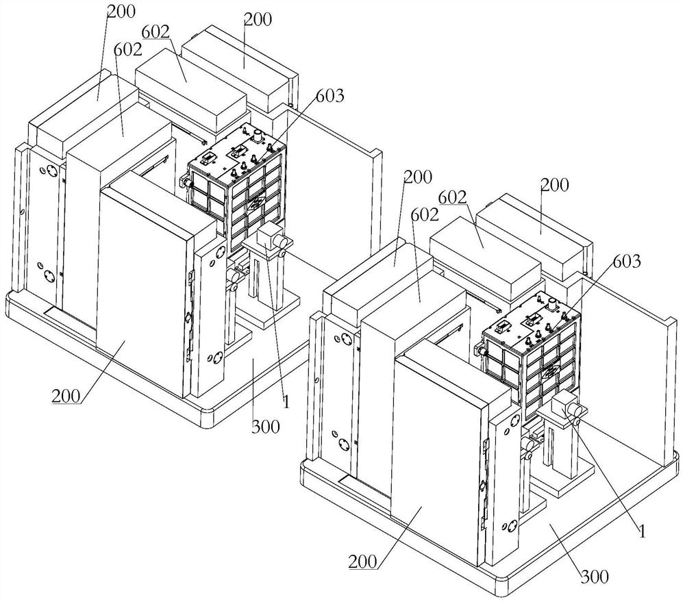
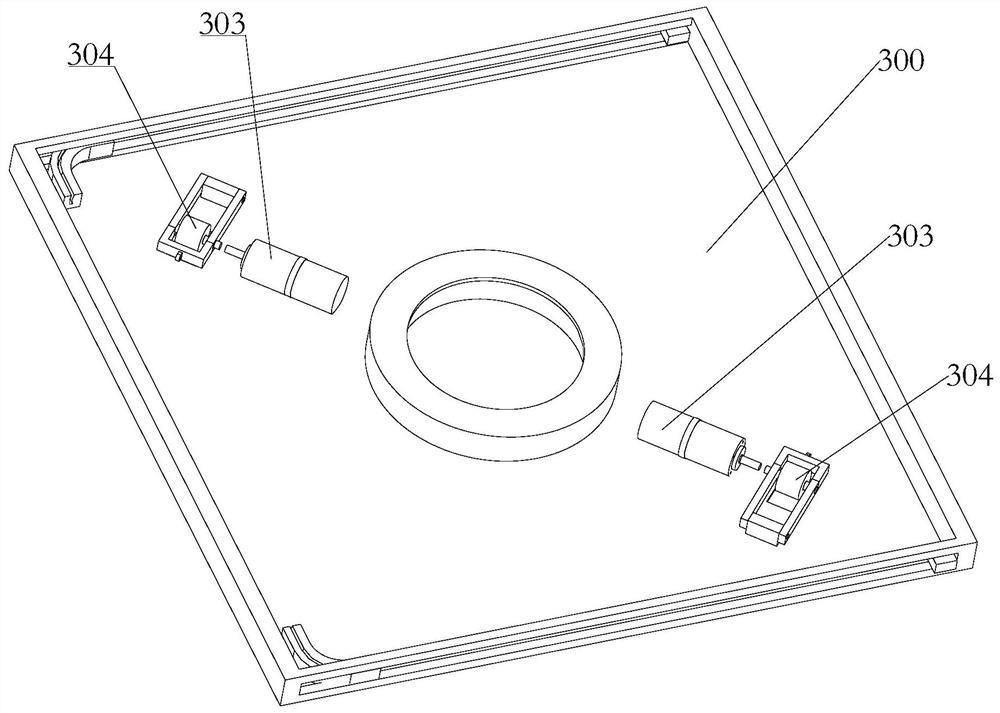
[0101] like figure 2 As shown, the rotating mechanism of this embodiment includes:
[0102] A driving motor 303, the driving motor 1 303 is installed on the force bearing mechanism 300 and is spaced from the base 600;
[0103] a friction wheel 304, the friction wheel 304 is installed on the driving end of the driving motor one 303;
[0104] The upper surface of the base 600 has a friction surface for friction transmission with the friction wheel 304, the driving motor 303 drives the friction wheel 304 to rotate, and the friction wheel 304 rotates and moves around the center of the base 600 along the friction surface, Then, the force-bearing mechanism 300 , the test box 200 and the optical inspection device on it are driven to rotate around the center of the base 600 .
[0105] Specifically, as figure 2 As shown, the driving end of the first driving motor 303 is radially arranged with the center of the base 600 ; the rotation mechanisms are two, and are arranged symmetrica...
Embodiment approach 2
[0107] The rotating mechanism of this embodiment includes a second drive motor, a first drive gear ring and a first drive gear. The second drive motor is installed on the force bearing mechanism and its driving end extends vertically downward. The first drive gear Installed on the driving end of the second drive motor; the first drive gear ring is installed in the middle of the base, the first drive gear meshes with the drive gear ring, and the second drive motor drives the drive gear to surround As soon as the driving gear ring makes a rotating motion, it drives the force-bearing mechanism, the test box and the optical inspection device on it to make a rotating motion around the center of the base. For details, reference may be made to the structure in which the rotating drive part cooperates with the drive gear in the third embodiment of the rotating mechanism. The rotary motion is realized by using the driving gear and the driving gear ring, the structure is simple, and the...
Embodiment approach 3
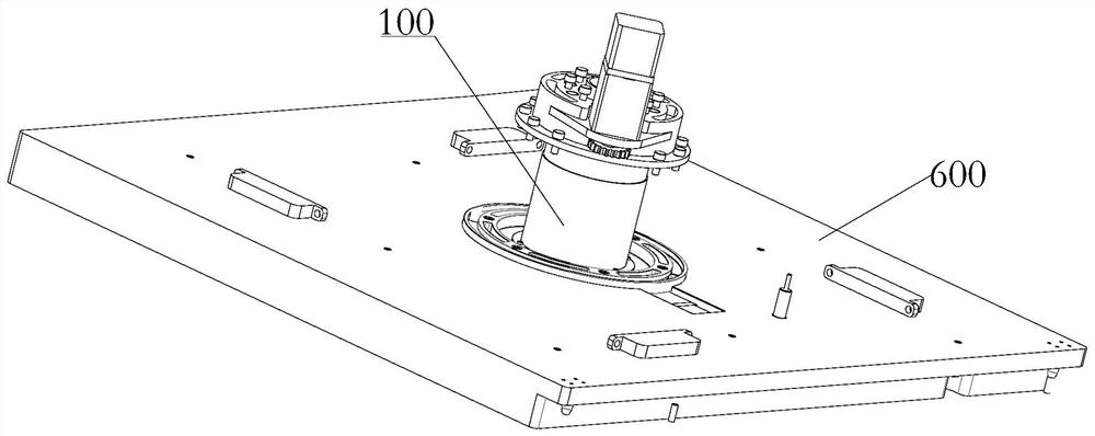
[0109] like Figure 3-Figure 12 As shown, the rotating mechanism of this embodiment needs to be implemented in conjunction with a lifting device. Specifically, the lifting device 100 is installed on the base 600, and the lifting end of the lifting device 100 is connected to the rotating mechanism and drives the Rotary mechanism lifts. The setting of the lifting device can facilitate the avoidance of structures such as antennas in the space station during the rotation process.
[0110] Wherein, a specific solution of the lifting device 100 is as follows: Figure 3-Figure 12 As shown, the lifting device includes:
[0111] Driving slip ring 101, the driving slip ring 101 is installed on the driving end of the elevating driving part 112, and rotates under the driving of the elevating driving part 112, the side wall of the driving slip ring 101 is provided with a spiral slideway 107;
[0112] Lifting slip ring 102, the lifting slip ring 102 is sleeved in the driving slip ring 10...
PUM
 Abstract
Description
Claims
Application Information
 - R&D
- Intellectual Property
- Life Sciences
- Materials
- Tech Scout
- Unparalleled Data Quality
- Higher Quality Content
- 60% Fewer Hallucinations
Browse by: Latest US Patents, China's latest patents, Technical Efficacy Thesaurus, Application Domain, Technology Topic, Popular Technical Reports.
© 2025 PatSnap. All rights reserved.Legal|Privacy policy|Modern Slavery Act Transparency Statement|Sitemap|About US| Contact US: help@patsnap.com