Laser welding device and laser welding method

A laser welding and laser technology, applied in laser welding equipment, using optical devices, measuring devices, etc., can solve problems such as deviation of measured values, inability to measure with high precision, and achieve the effect of suppressing storage capacity

Active Publication Date: 2020-05-01
PANASONIC INTELLECTUAL PROPERTY MANAGEMENT CO LTD
View PDF8 Cites 0 Cited by
  • Summary
  • Abstract
  • Description
  • Claims
  • Application Information

AI Technical Summary

Problems solved by technology

In this case, there is a problem that a depth shallower than the actual deepest part of the small hole is measured, and the measured value varies, making it impossible to measure with high precision.

Method used


Image

  • Laser welding device and laser welding method
  • Laser welding device and laser welding method
  • Laser welding device and laser welding method

Examples


other Embodiment approach

[0137] Regarding the above-mentioned embodiment, the following configurations may also be adopted.

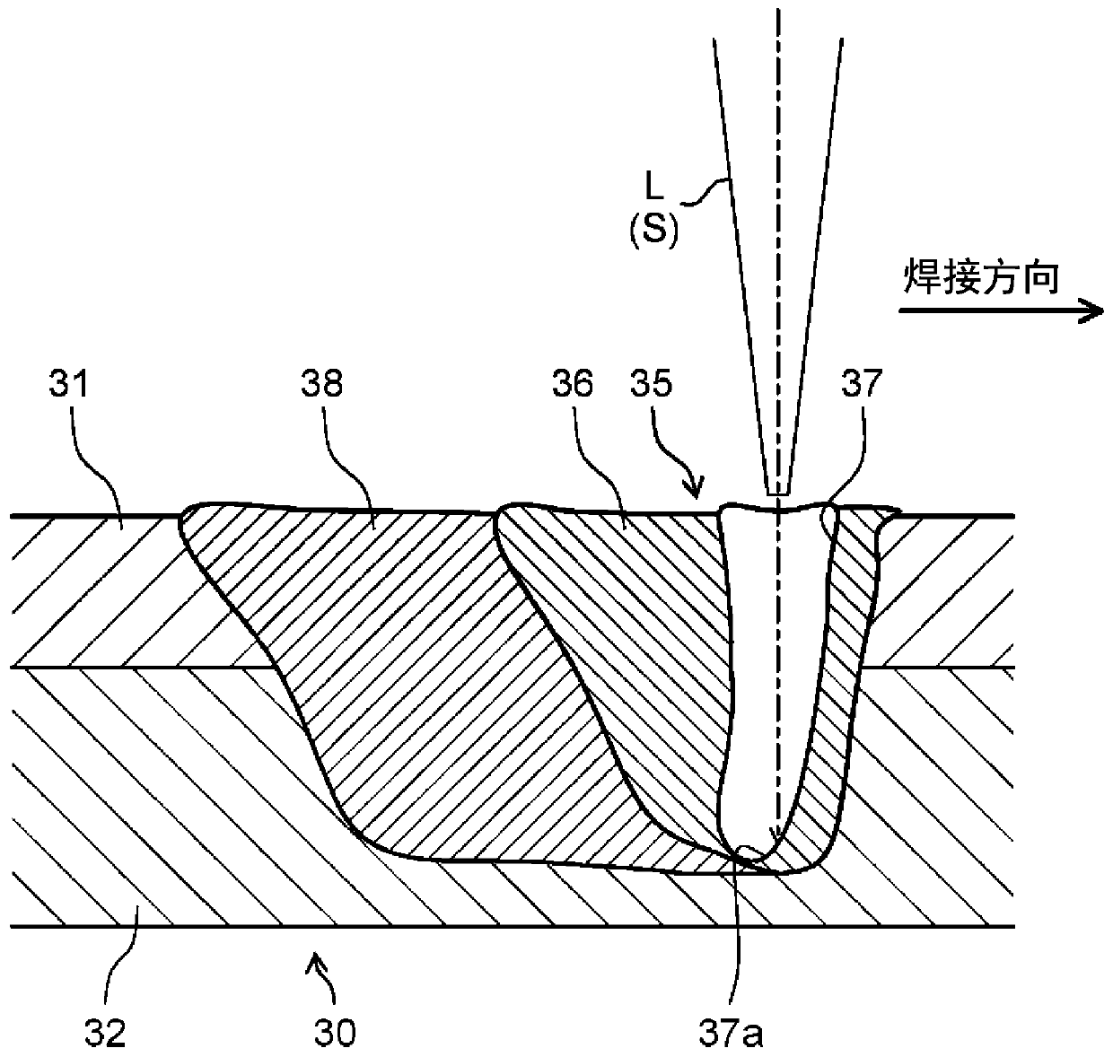
[0138] In this embodiment, the trajectory of the spin-orbit 40 may be not only a simple spiral shape, but also a polygonal shape such as a circle or a quadrangle. Additionally, if Figure 10 As shown, the elliptical trajectory may be formed discontinuously. That is, as long as it is a continuous trajectory capable of irradiating the measuring light S inside the small hole 37 , various shapes can be adopted. In addition, the rotation direction of the irradiation of the spin track 40 with respect to the welding direction of the laser light L may be clockwise or counterclockwise.

[0139] In addition, in the present embodiment, the laser light L and the measurement light S are moved and irradiated in a spiral shape along the linear welding path 34 , but the welding path is not limited to the linear shape. For example, consider a case where the laser irradiation head 20 is moved...


PUM


Abstract

Provided is a laser welding device (10) for welding a weld part (35) by means of a laser beam (L), the laser welding device being provided with: a laser irradiation head (20) which irradiates the weldpart (35) with the laser beam (L) and measurement light (S) having a wavelength different from that of the laser beam (L) such that the laser beam (L) and the measurement light (S) coaxially overlapwith each other; a measurement unit (14) which repeatedly measures a welding penetration depth at the weld part (35) on the basis of the measurement light (S) that has been emitted from the laser irradiation head (20) and that has been reflected on the weld part (35); and a determination unit (17) which determines the welding penetration depth at the weld part (35) on the basis of a plurality of extracted measurement values that is a portion of a plurality of welding penetration depth measurements taken by the measurement unit (14) and that is distributed within a prescribed range determined using, as a reference, the measurement value of the welding penetration depth at the deepest side, or on the basis of the average value of the plurality of extracted measurement values.

Description

technical field [0001] The present disclosure relates to a laser welding device and a laser welding method. Background technique [0002] Conventionally, there is known a laser welding device that evaluates the quality of a welded portion by directly measuring the penetration depth of the welded portion (for example, refer to Patent Document 1). [0003] Patent Document 1 discloses a configuration in which laser light and measurement light are coaxially superimposed to irradiate the inside of the small hole of the welding portion, and the measurement light reflected from the bottom of the small hole enters an optical interferometer through a beam splitter. Here, in the optical interferometer, since the optical path length of the measurement light can be measured, the depth of the small hole is determined as the penetration depth of the welded portion based on the measured optical path length. [0004] prior art literature [0005] patent documents [0006] Patent Document...

Claims


Application Information

Patent Timeline
IPC IPC(8): B23K26/21B23K26/00
CPCB23K26/032B23K26/082B23K31/125B23K26/064B23K26/24B23K26/21B23K26/0643B23K26/0648G01B11/22
Inventor 酒井徹樱井通雄
Owner PANASONIC INTELLECTUAL PROPERTY MANAGEMENT CO LTD
Why Eureka
Try Eureka