
Backlight module and display device

A backlight module and light mixing technology, applied in optics, nonlinear optics, instruments, etc., can solve the problems of thick backlight module thickness, poor light mixing uniformity, and a large number of light-emitting sources, so as to improve the uniformity of light color. performance, achieve ultra-thin design, and reduce the number of uses

Inactive Publication Date: 2020-05-01
SHENZHEN DREAM & HOPE DISPLAY TECH CO LTD
View PDF18 Cites 9 Cited by
  • Summary
  • Abstract
  • Description
  • Claims
  • Application Information

AI Technical Summary

Problems solved by technology

[0005] The purpose of the present invention is to provide a backlight module to solve the technical problems of thick backlight module, large number of light sources, poor light mixing uniformity, high production cost and low yield rate.

Method used


Image

  • Backlight module and display device
  • Backlight module and display device
  • Backlight module and display device

Examples


Embodiment Construction

[0028] In order to make the object, technical solution and advantages of the present invention clearer, the present invention will be further described in detail below in conjunction with the accompanying drawings and embodiments. It should be understood that the specific embodiments described here are only used to explain the present invention, not to limit the present invention.

[0029] It should be noted that when a component is referred to as being “fixed on” or “disposed on” another component, it may be directly or indirectly located on the other component. When an element is referred to as being "connected to" another element, it can be directly or indirectly connected to the other element. The orientation or positional relationship indicated by the terms "upper", "lower", "left", "right", etc. are based on the orientation or positional relationship shown in the drawings, and are for convenience of description only, rather than indicating or implying the referred device...


PUM

PropertyMeasurementUnit
thicknessaaaaaaaaaa
reflectanceaaaaaaaaaa
transmittivityaaaaaaaaaa

Abstract

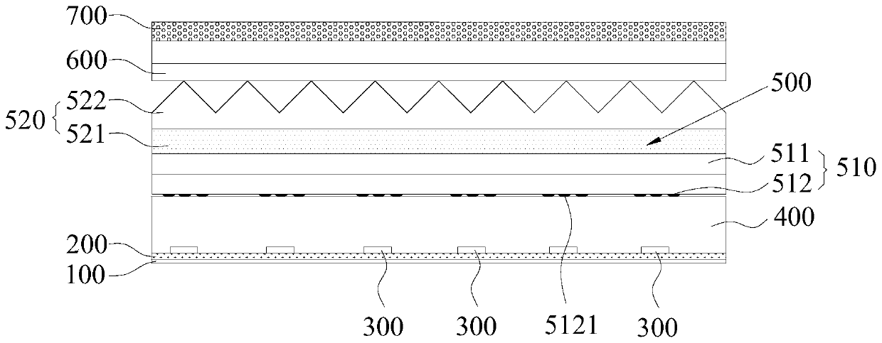
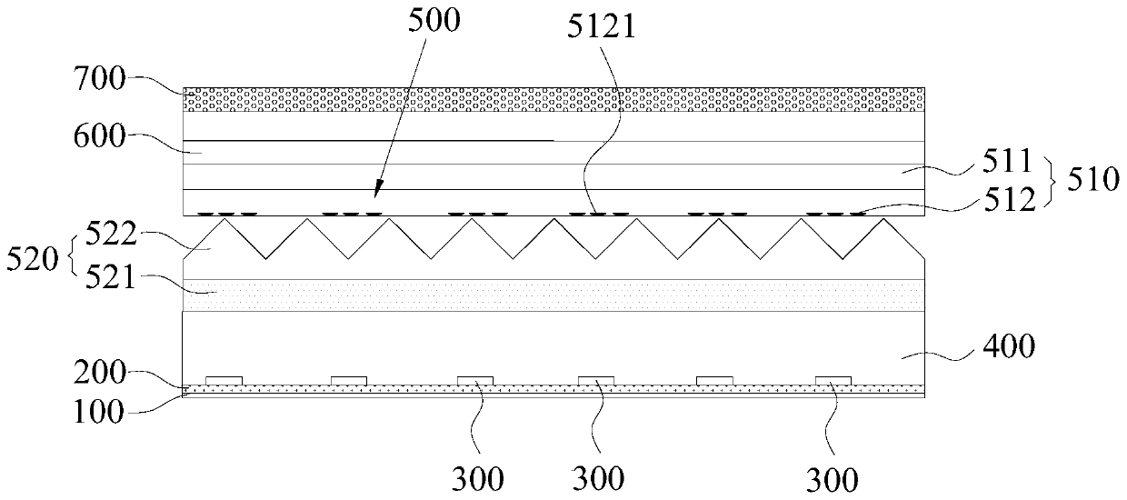
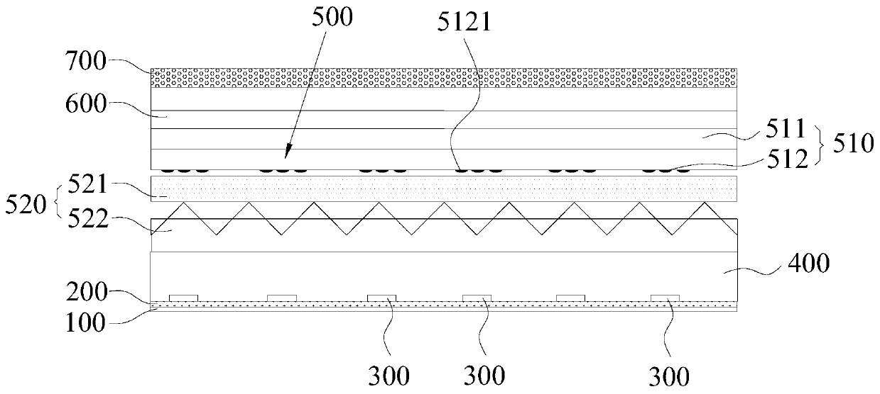
A backlight module and a display device. The backlight module comprises multiple monochromatic light-emitting units (300), a transparent package layer (400) covered on the monochromatic light-emittingunit (300), a brightening layer (600) covered right above the package layer (400), and a composite function structure (500) provided between the package layer (400) and the brightening layer (600) and covering the package layer (400). By using the monochromatic light-emitting units (300) as a light source, the backlight module converts the monochromatic light into a compound light by means of thecomposite function structure (500), and reflects and scatters the light before emitting so as to reduce the number of monochromatic light-emitting units (300) and reduce the cost of a material. In addition, in addition to the light conversion function, the composite function structure (500) can also be composite with other optical functions. In this way, the thickness of the backlight module canbe reduced so as to achieve the ultra-thin design, simplify the manufacturing process, and reduce the manufacturing cost.

Description

technical field [0001] The invention belongs to the field of display technology, and more specifically relates to a backlight module and a display device. Background technique [0002] Liquid crystal display technology is currently the mainstream display technology in the market, and has been widely used in mobile phones, tablet computers, personal computers, televisions, vehicle displays, industrial control displays and other fields. The liquid crystal itself does not have the function of emitting light, so a backlight module is usually used to provide a backlight for it. As we all know, the current backlight module mainly uses polychromatic white light-emitting diodes (Light Emitting Diode, LED) as the light source, and is composed of multiple layers of optical film structures such as light guide plates, diffusion films, and light-enhancing layers that are closely arranged in sequence. The structural forms mainly include side entry type and direct type. [0003] Specific...

Claims


Application Information

Patent Timeline
Patent Type & Authority Applications(China)
IPC IPC(8): G02F1/13357
CPCG02F1/133611G02F1/133609G02F1/133606G02F1/133605G02F1/133603G02F1/133614G02F1/133607
Inventor 曹庆刘瀚潘业琥
Owner SHENZHEN DREAM & HOPE DISPLAY TECH CO LTD
Features
  • Generate Ideas
  • Intellectual Property
  • Life Sciences
  • Materials
  • Tech Scout
  • Unparalleled Data Quality
  • Higher Quality Content
  • 60% Fewer Hallucinations
Learn More