Servo control device

A servo control device and mechanical technology, applied in the field of servo control devices for target tracks, can solve problems such as change in correction amount, inability to uniquely determine correction amount, mechanical vibration, etc.

Active Publication Date: 2020-05-01
MITSUBISHI ELECTRIC CORP
View PDF13 Cites 3 Cited by
  • Summary
  • Abstract
  • Description
  • Claims
  • Application Information

AI Technical Summary

Problems solved by technology

In this case, when the estimated value of the fingertip position is on the angle bisector of the specified angle, the vertical feet of the vertical line exist on two sides, and the correction amount cannot be uniquely determined.
In addition, when the direction or length of the vertical line changes rapidly, the correction amount changes rapidly, and there is a problem that shock is applied to the machine and vibration is caused.

Method used


Image

  • Servo control device
  • Servo control device
  • Servo control device

Examples


Embodiment approach 1

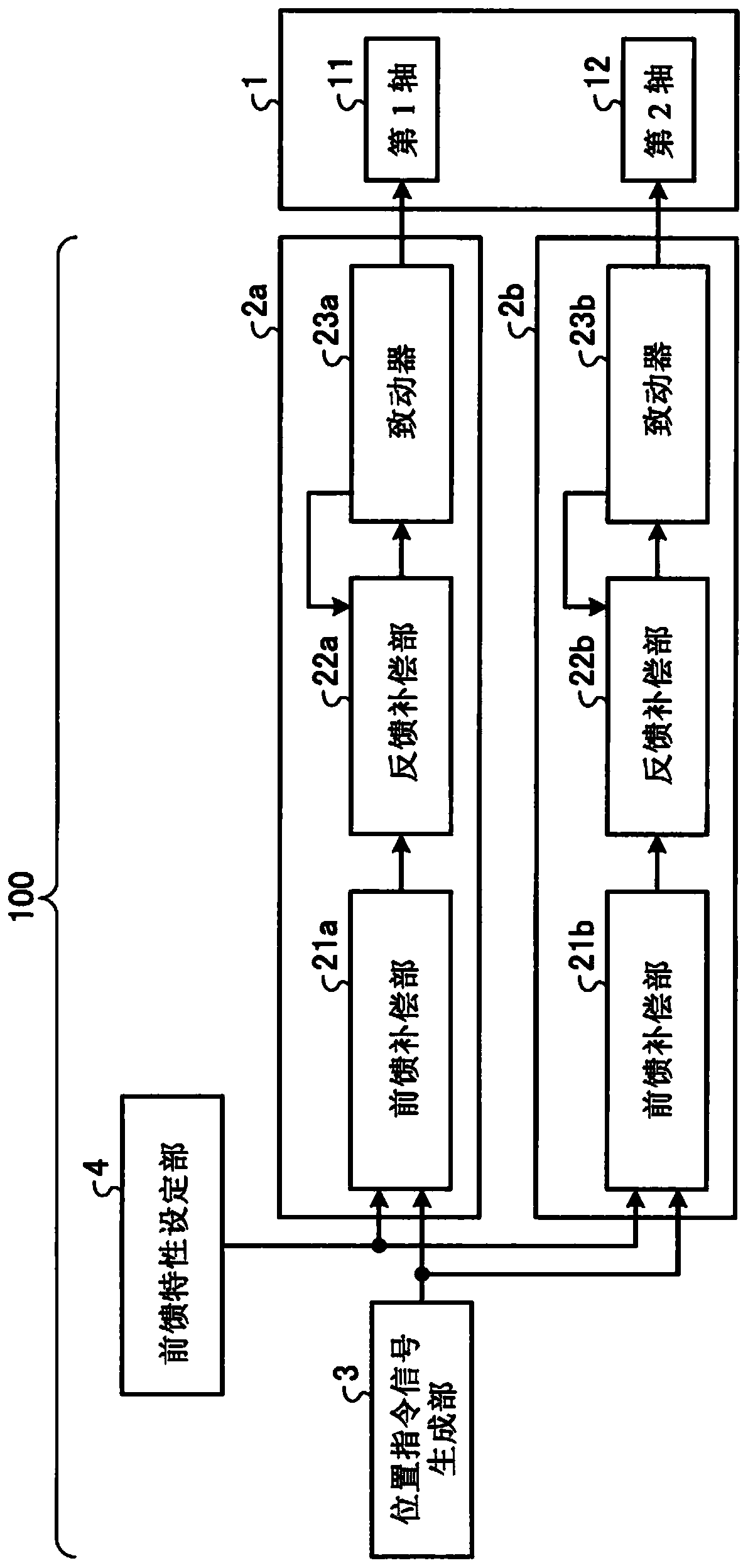
[0027] figure 1 It is a block diagram showing a schematic configuration of the servo control device 100 according to Embodiment 1 of the present invention. The servo control device 100 takes a machine having one or more drive shafts as a control object and performs trajectory following control, which controls the mechanical end of the machine to follow a set target trajectory with high precision. Here, the machine to be controlled by the servo control device 100 is the horizontal articulated robot 1 . The servo control device 100 includes a first-axis servo control unit 2 a , a second-axis servo control unit 2 b , a position command signal generation unit 3 , and a feedforward characteristic setting unit 4 . The first-axis servo control unit 2 a and the second-axis servo control unit 2 b drive and control the horizontal articulated robot 1 .

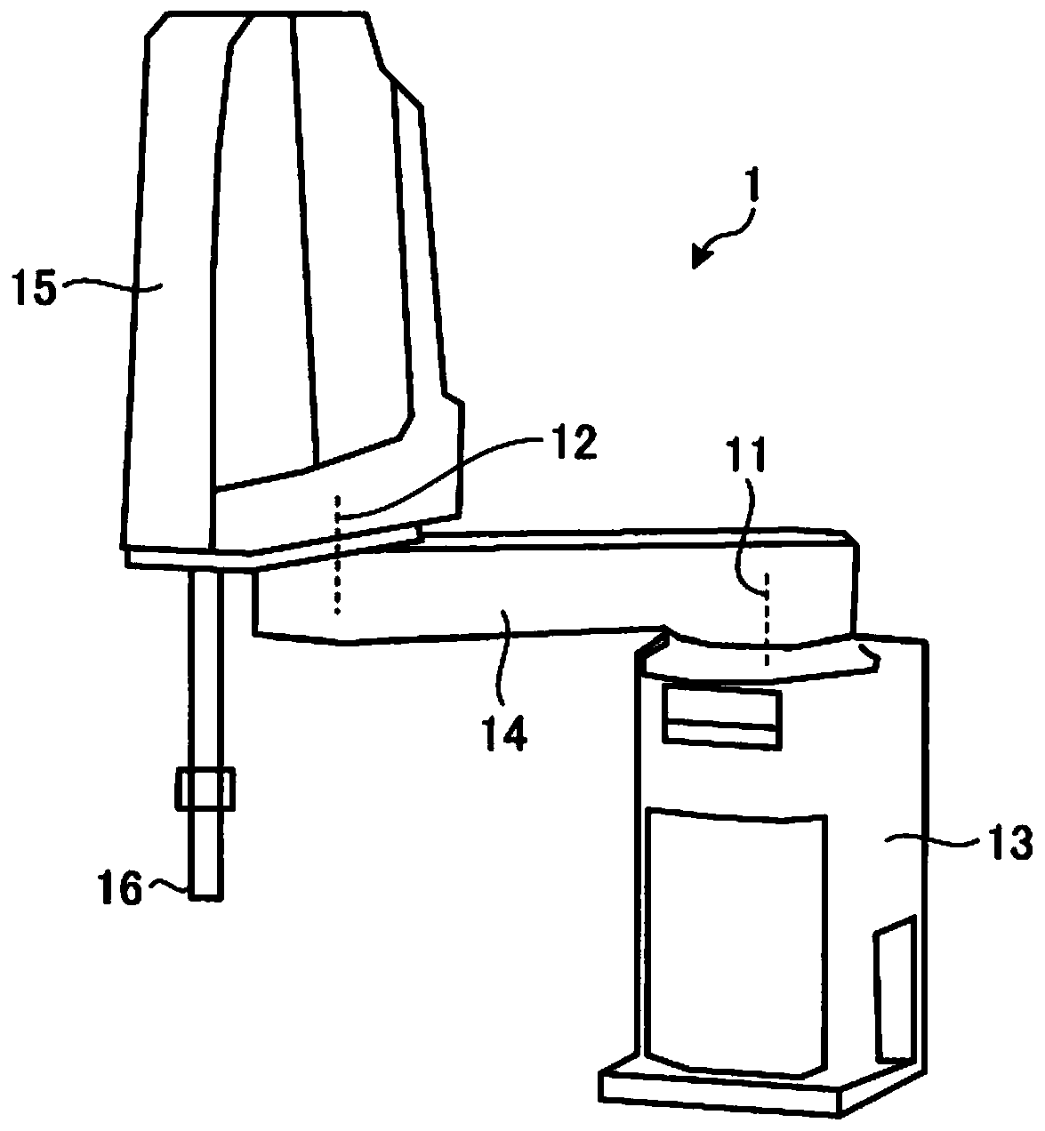
[0028] figure 2 It is a schematic diagram showing the horizontal articulated robot 1 according to the first embodiment. The horizo...

Embodiment approach 2

[0093] Figure 8 It is a block diagram showing a schematic configuration of the servo control device 200 according to Embodiment 2 of the present invention. The servo control device 200 includes a first-axis servo control unit 2a', a second-axis servo control unit 2b', a position command signal generation unit 3, and a feedforward characteristic setting unit 4. The first-axis servo control unit 2a' and the second-axis servo control unit 2b' drive and control the horizontal articulated robot 1 .

[0094] The difference between the servo control device 200 according to the second embodiment and the servo control device 100 according to the first embodiment is that the first axis servo control unit 2 a ′ and the second axis servo control unit 2 b ′ are different from the first axis servo control unit 2 a ′. 2a and the second axis servo control unit 2b are different. That is, in the first axis servo control unit 2a', the vibration suppression compensation unit 24a is added betwe...

Embodiment approach 3

[0105] Figure 10 It is a block diagram showing a schematic configuration of the servo control device 300 according to Embodiment 3 of the present invention. The servo control device 300 includes a first-axis servo control unit 2a, a second-axis servo control unit 2b, a position command signal generation unit 3, and a feedforward characteristic setting unit 4a. The first-axis servo control unit 2 a and the second-axis servo control unit 2 b drive and control the horizontal articulated robot 1 .

[0106] The servo control device 300 according to the third embodiment differs from the servo control device 100 according to the first embodiment in that the feedforward characteristic setting unit 4 a is different from the feedforward characteristic setting unit 4 . The transfer functions set by the feedforward characteristic setting unit 4 a and the transfer function set by the feedforward characteristic setting unit 4 for each of the feedforward compensation units 21 a and 21 b ar...


PUM


Abstract

The present invention provides a servo control device (100) which drives a machine (1) by means of actuators (23a, 23b) and thereby performs control such that an end of the machine (1) follows a set target trajectory. The servo control device (100) is provided with feedforward compensation units (21a, 21b) which output the feedforward signals for controlling the actuators(23a, 23b), on the basis of an input position command signal, and thereby perform feedforward compensation, wherein the input-to-output characteristics of the feedforward compensation units (21a, 21b) in a continuous-time system are represented by a transfer function having an unstable zero point, and the feedforward compensation units (21a, 21b) produce a step response having a reverse swing.

Description

technical field [0001] The present invention relates to a servo control device that controls a machine end of a machine to be controlled to follow a set target trajectory. Background technique [0002] In industrial machines such as robotic arms that perform processing, assembly, sealing, or welding, the servo control device controls the servo motors that are installed on the drive shafts such as the joint shafts of the machine so that the position of the mechanical end of the machine follows Pre-set target tracks. In this control, the operating speed in the direction of each axis or the rotation speed around each axis changes abruptly at the corner of the target trajectory, so that the machine tends to vibrate. [0003] Therefore, in normal servo control, in order to suppress this mechanical vibration, the command signal for each axis is locally smoothed by a filter on a time basis, thereby suppressing a change in the command position. , but as a result, a trajectory erro...

Claims


Application Information

Patent Timeline
Patent Type & Authority Applications(China)
IPC IPC(8): G05B11/36
CPCG05B11/011G05B19/404G05B2219/41431G05B2219/42077G05B2219/41122B25J9/1651B25J9/1664G05B11/36G05B19/19G05B2219/39241G05B2219/41199G05B2219/41428
Inventor 斋藤晓生池田英俊
Owner MITSUBISHI ELECTRIC CORP
Why Eureka
Try Eureka