Dimmer system

A dimming and channel technology, applied in the field of dimming systems, which can solve problems such as interference and customer costs

Active Publication Date: 2020-05-01
SIEMENS SWITZERLAND
View PDF4 Cites 0 Cited by
  • Summary
  • Abstract
  • Description
  • Claims
  • Application Information

AI Technical Summary

Problems solved by technology

Cost and disruption on the part of the customer due to possible required equipment replacement

Method used


Image

  • Dimmer system
  • Dimmer system
  • Dimmer system

Examples


Embodiment Construction

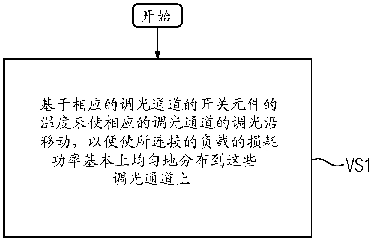
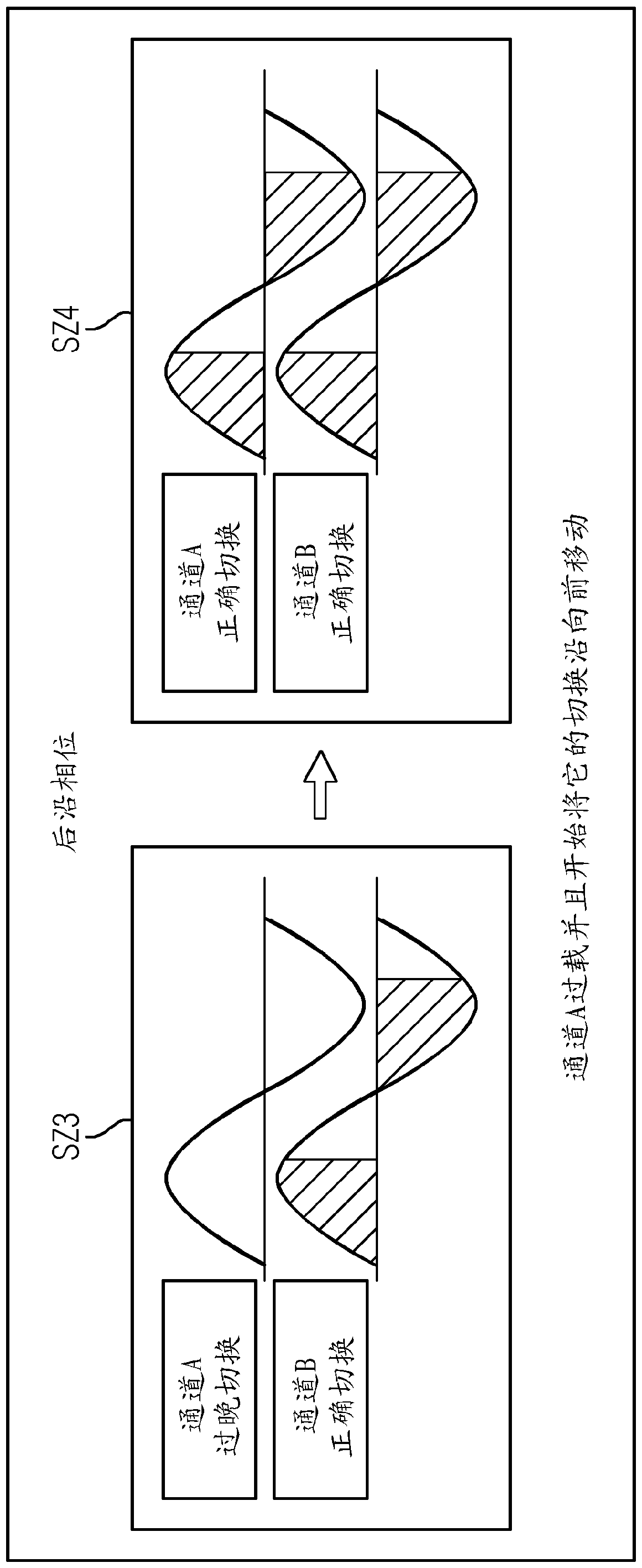
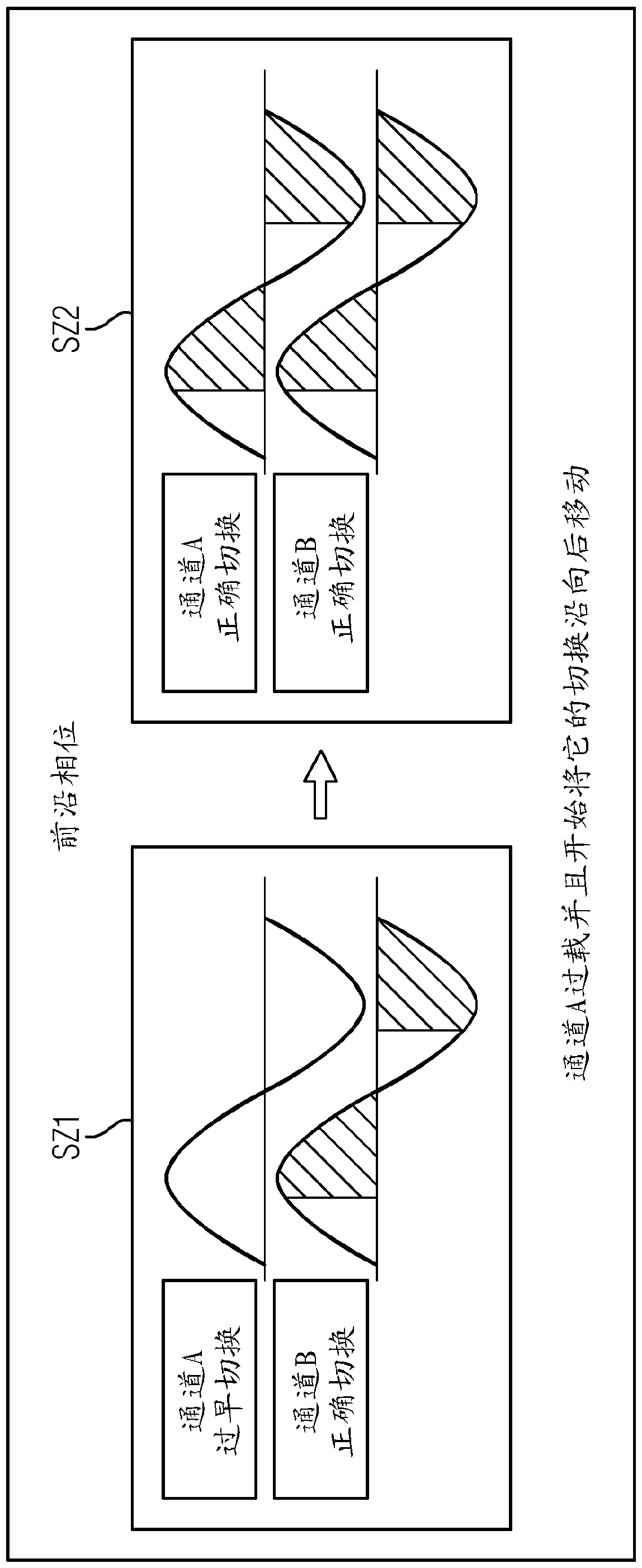
[0020] In the market of lighting devices, LED technology is advancing, whereby the power requirements for dimming channels have decreased. Attempts were made to accommodate multiple channels with the same overall dimensions, which, although supporting less power, thus offer greater flexibility and are optimized for LED lamps. If a more powerful load (eg light bulb chandeliers) should now be operated all at once, several channels can be paralleled for this purpose to form a more performant logic channel. This has the result that the load current is distributed over the channels connected in parallel and thus the power loss is evenly distributed. However, this only works if all channels are switched on or off at the same point in time. If this is not the case, the current in one or more channels is increased and these channels may be overloaded and cut off. The more channels that should be switched together, the bigger the problem. This problem is prevented or reduced with th...


PUM


Abstract

The invention relates to a dimmer system and method for controlling the power consumption of a load that can be connected to a dimmer system, in particular an LED lamp, wherein the dimmer system comprises at least two parallel-connected galvanically isolated dimming channels, wherein a shifting of the dimming edge of the respective dimming channel occurs according to the temperature of the switchelements of the respective dimming channel, in order to distribute the power dissipation of the connected load substantially equally to the dimming channels.

Description

technical field [0001] The invention relates to a dimming system for controlling the power consumption of a load connectable to the dimming system, in particular an LED lighting device, wherein the dimming system comprises at least two parallel-connected, current-separated dimming channels. The invention also relates to a method for controlling the power consumption of a load connectable to a dimming system. Background technique [0002] Dimmers or dimming devices or dimming systems for brightness control are generally known and are used to vary the power of lighting devices. This power change can be achieved by leading-edge phase control or trailing-edge phase control. In the case of leading-edge phase control, the current is switched on with a delay after the zero crossing of the alternating voltage and flows until the next current zero crossing. In the case of trailing phase control, however, the current is switched on immediately after a zero crossing and switched off ...

Claims


Application Information

Patent Timeline
IPC IPC(8): H05B45/30H05B44/00
CPCH05B39/044H05B39/048Y02B20/00H05B45/56H05B45/18H05B39/04H05B44/00
Inventor J.门施J.雷斯虎伯
Owner SIEMENS SWITZERLAND
Why Eureka
Try Eureka