
Embedded oven

An embedded and oven technology, applied in the direction of roaster/barbecue grid, kitchen utensils, household utensils, etc., can solve problems such as scalding users, box rust, temperature rise, etc., to prolong service life, avoid hot hands, and ensure stable effect

Active Publication Date: 2020-05-05
NINGBO FOTILE KITCHEN WARE CO LTD
View PDF10 Cites 2 Cited by
  • Summary
  • Abstract
  • Description
  • Claims
  • Application Information

AI Technical Summary

Problems solved by technology

The control components of the oven are generally arranged above the door body. The air from the fan in the heat dissipation channel can dissipate the heat out of the oven box and at the same time dissipate heat from the control components. Limited heat dissipation
[0003] The heat in the oven is discharged through the gap above the oven door, which not only makes the hot air spray directly to the user, but also reduces the user's experience, and sometimes the hot air even burns the user
In addition, the hot air will heat the door body, making the temperature of the oven door body further increase on the basis of the heat transfer and radiation of the air in the inner tank, and finally cause the highest temperature outside the oven door glass to be as high as about 80°C when the oven is working normally. Adults will feel hot when touching the outside of the door with their hands
[0004] In addition, the built-in oven is generally placed at the bottom of the cabinet. Due to the needs of cooking operations, the kitchen floor is generally relatively humid, especially the floor below the oven, which is not easy to clean during daily cleaning. The oven is placed in this environment for a long time , not only will cause the box to rust and affect the service life of the oven, but also the humid environment is easy to breed bacteria, so when using the oven for baking operations, the baked food has the risk of being contaminated by bacteria

Method used


Image

  • Embedded oven
  • Embedded oven
  • Embedded oven

Examples


Embodiment Construction

[0030] The present invention will be further described in detail below in conjunction with the accompanying drawings and embodiments.

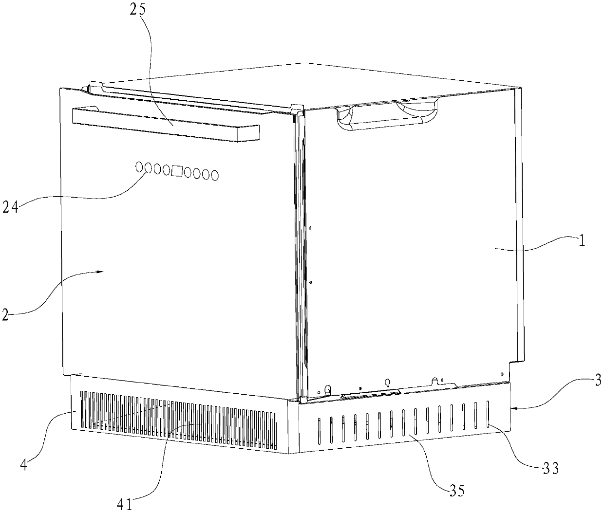
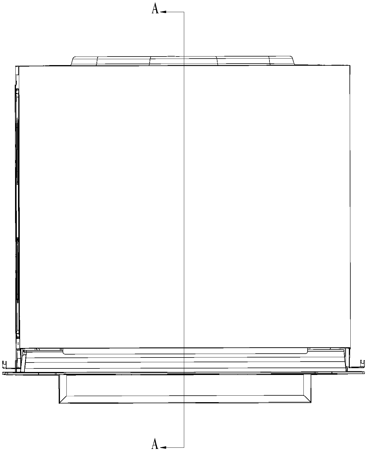
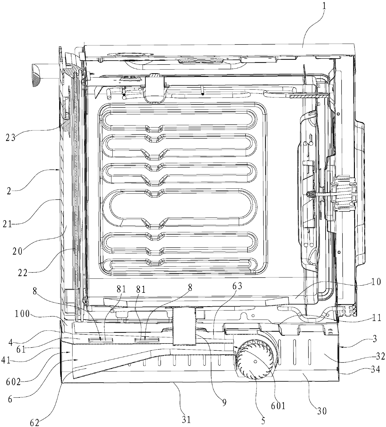
[0031] Such as Figure 1~6 As shown, a built-in oven includes a door body 2 and a box body 1, and the box body 1 is provided with an inner container 10 and a ventilation pipe 9, and the above-mentioned door body 2 includes an outer glass 21 and a door behind the outer glass 21. The middle glass 22 has a ventilation gap 20 between the outer glass 21 and the middle glass 22 . The bottom of the bottom plate 11 of the above-mentioned box body 1 is provided with a base 3 that matches it. The base 3 includes a lower base plate 31, a left side plate 32, a right side plate 33 and a back side plate 34. The lower base plate 31 is parallel to the above-mentioned base plate 11 and Located below the bottom plate 11, the above-mentioned left side plate 32, right side plate 33 and back side plate 34 are enclosed between the bottom plate 11 and the lower bot...


PUM


Abstract

The invention relates to an embedded oven. The embedded oven comprises a door body, an embedded oven body and a controller, the door body comprises outer glass and middle glass arranged behind the outer glass, a ventilation gap is reserved between the outer glass and the middle glass, a cold air channel is further formed in the bottom of the embedded oven body, outlet air of the cold air channel leads to the ventilation gap, and the controller is arranged in the ventilation gap. Compared with the prior art, according to the invention, the cold air channel can blow cold air to the ventilation gap; according to the oven, the door body can be fully and effectively cooled, hands are prevented from being scalded due to the fact that the temperature of the oven door body is too high, the controller arranged in the gap can be effectively cooled, and therefore the stability of the performance of the controller is guaranteed, the oven can stably operate, and the service life of the oven is prolonged.

Description

technical field [0001] The invention relates to the field of household cooking devices, in particular to an embedded oven. Background technique [0002] The oven is a common cooking device in modern kitchens, which can be used to bake roast chicken, roast duck, bake bread, pastries, etc. When the oven is working normally, the temperature of the inner tank is very high. Generally, the heat inside the oven is led to the heat dissipation channel arranged on the top of the oven through the ventilation pipe, and then the heat is brought to the outside of the oven through the channel. For example, the application number is 201611207999.2 (publication number It is the oven structure disclosed in the Chinese invention patent "A Kind of Oven" of CN106764974A). The control components of the oven are generally arranged above the door body. The air from the fan in the heat dissipation channel can dissipate the heat out of the oven box and at the same time dissipate heat from the contro...

Claims


Application Information

Patent Timeline
Patent Type & Authority Applications(China)
IPC IPC(8): A47J37/06
CPCA47J37/0623A47J37/0664
Inventor 罗灵杨均曹骥
Owner NINGBO FOTILE KITCHEN WARE CO LTD
Learn More