Kitchen waste transfer tank

A technology for kitchen waste and transfer boxes, which is applied in the directions of garbage receptacle, transportation and packaging, can solve the problems of limited single feeding capacity, limited feeding capacity, and large size of the space occupied by the container, and achieves the limit capacity. Simple and reliable, increased pouring angle, reliable and strong power

Pending Publication Date: 2020-05-05
SHENZHEN LEO KING ENVIRO GRP CO LTD
View PDF0 Cites 0 Cited by
  • Summary
  • Abstract
  • Description
  • Claims
  • Application Information

AI Technical Summary

Problems solved by technology

[0008] 2. The locking structure of the tailgate of the box body is complicated
[0011] 5. The guide rail of the feeding mechanism adopts the traditional one-piece guide rail, which affects the dumping angle of the trash can
[0012] 6. The internal anti-material accumulation mechanism has limited material removal capacity
The feeding mechanism is set inside the box to prevent the material from accumulating under the feeding port. The feeding mechanism of the equipment mentioned above is suspended and swing arm type feeding. The length of the swing arm and the width of the swing arm plate determine its small moment. Limited capacity for single feeding
[0013] 7. The space occupied by the box is large
[0014] 8. Poor compatibility of the box to the hook-arm truck
The above-mentioned box is only compatible with the hook-arm trucks with hydraulic tail reserved on the market, and there are certain restrictions on the selection of the hook-arm trucks (in addition to the above-mentioned reserved forms, the hook-arm trucks on the market also have electric plug-type reservations)

Method used


Image

  • Kitchen waste transfer tank
  • Kitchen waste transfer tank
  • Kitchen waste transfer tank

Examples


specific Embodiment approach

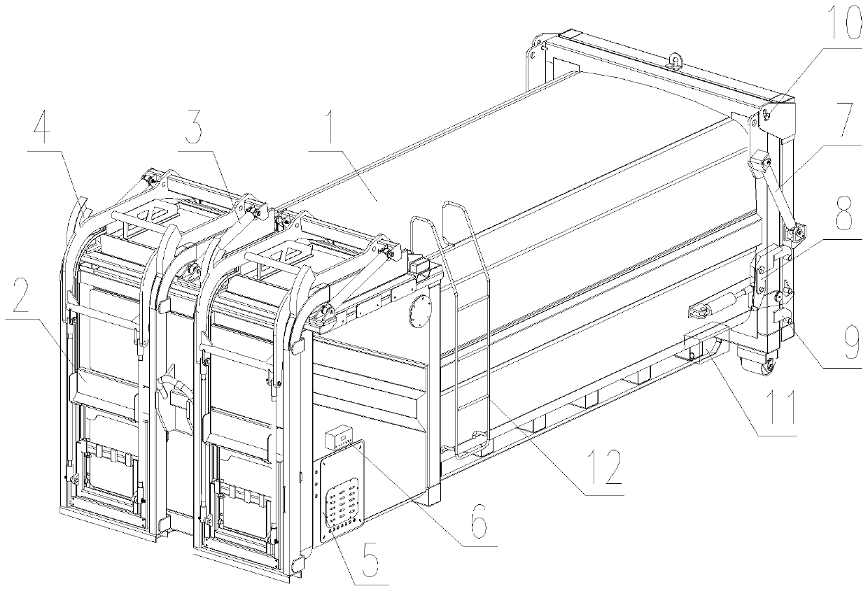
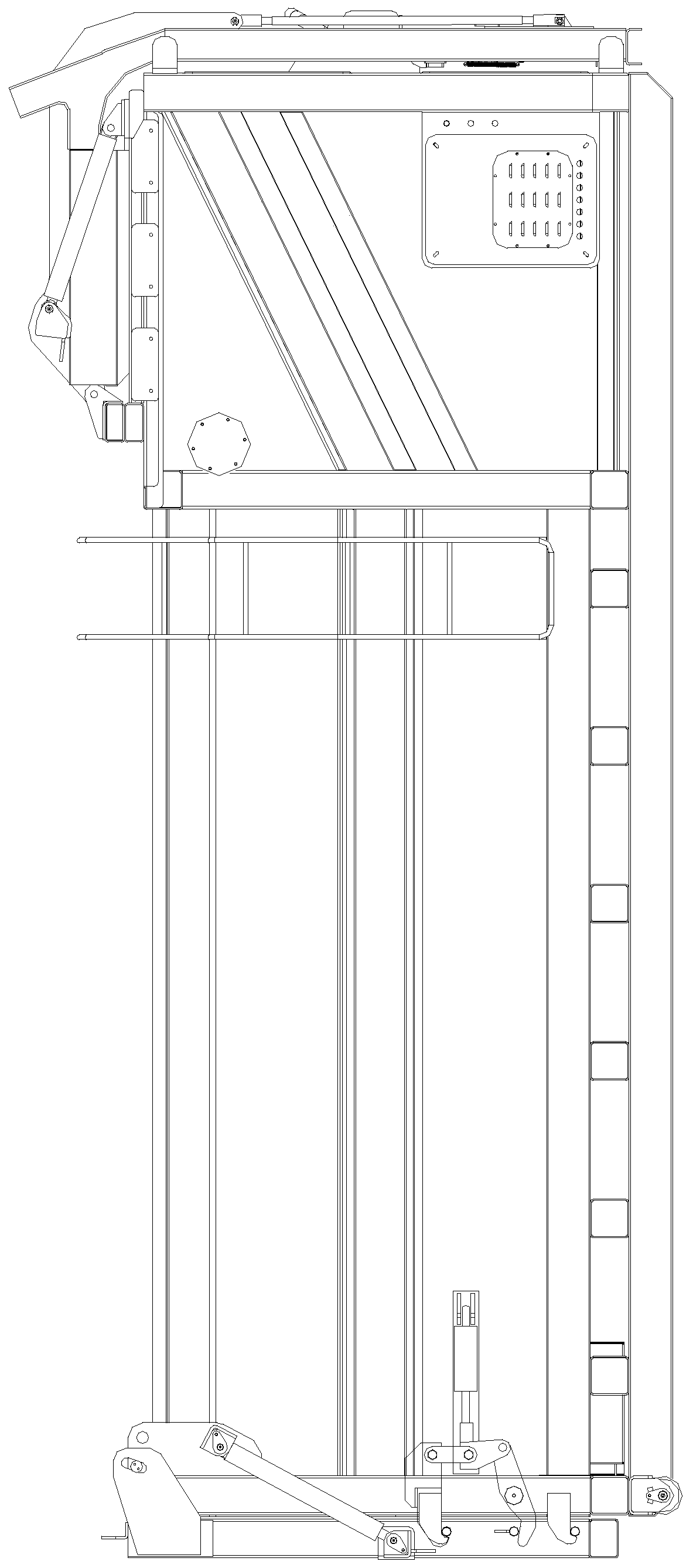
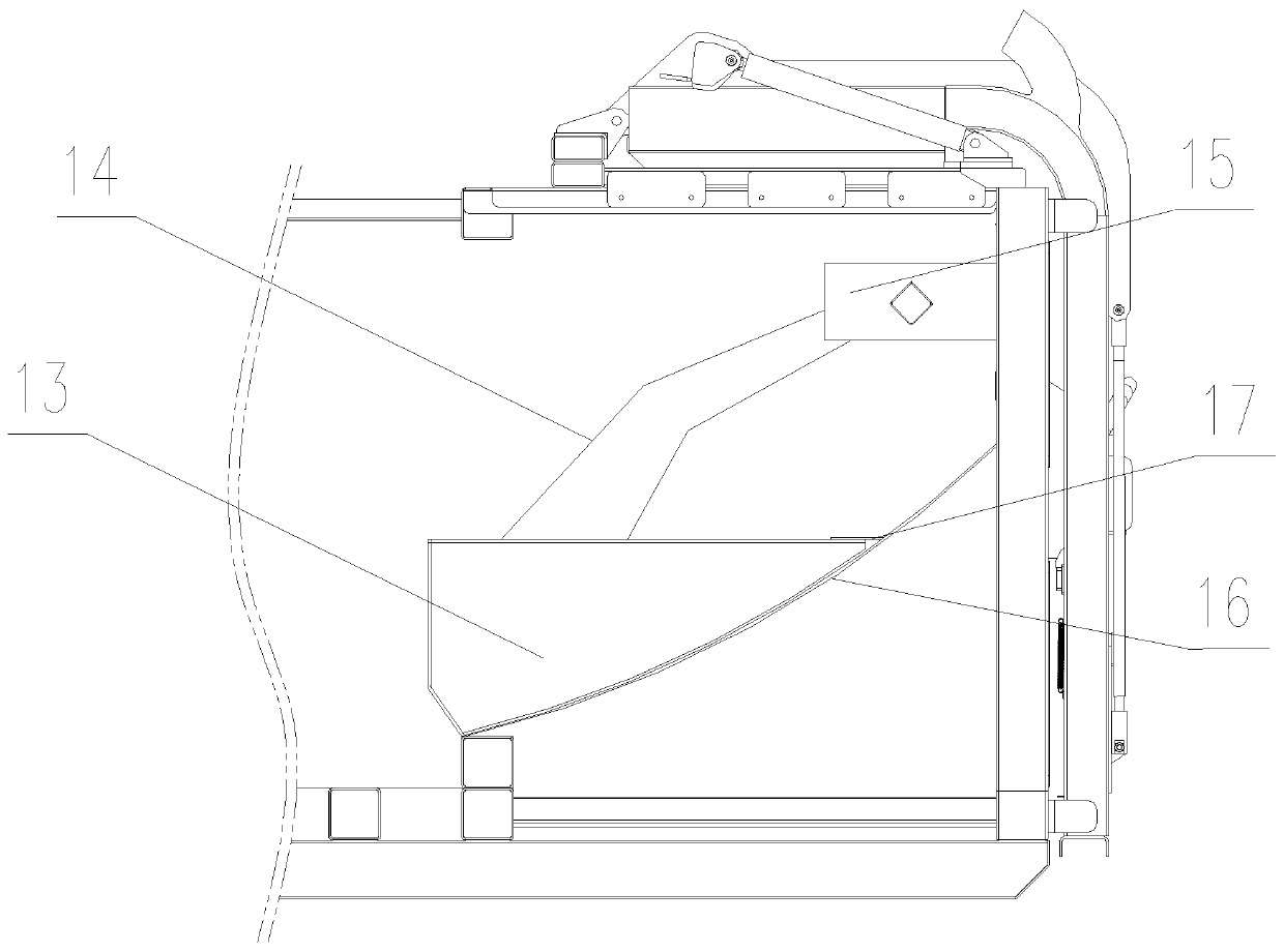
[0040] Such as Figure 1~5 As shown, it shows a specific embodiment of the present invention, a kind of food waste transfer box, comprising a square box 1, the front end of the square box hooks the box surface, and the rear end of the square box is equipped with a tailgate;

[0041] The hook box surface is equipped with a lifting device assembly for pouring garbage in the garbage can into the square box; Clamping mechanism; the lifting device assembly also includes a push hydraulic cylinder 3 that provides power for the hanging bucket lifting mechanism 2; the hanging bucket lifting mechanism 2 is fixedly installed on the guide rails on both sides by the rollers on both sides, and the guide rails on both sides Extending from the hook box surface to the garbage dump on the top surface of the square box body, the corner part of the guide rail is provided with an outer ear guide rail 4 that extends outward and is used to guide the rollers to the inside; the above also includes the...


PUM


Abstract

The invention discloses a kitchen waste transfer tank. The kitchen waste transfer tank is a square tank, so that refitting depending on an existing tank is convenient. By adopting outer lug guide rails, the design of two-section guide rails is achieved, the degree of freedom of overturning during garbage dumping is made larger, and more thorough dumping is facilitated. The kitchen waste transfer tank comprises the square tank. A tank hooking surface is arranged on the front end surface of the square tank, and a tail gate is mounted on the rear end surface of the square tank. A lifting device assembly used for pouring garbage in a garbage container into the square tank is mounted on the tank hooking surface. The lifting device assembly comprises container-hanging lifting mechanisms. The container-hanging lifting mechanisms comprise clamping mechanisms used for clamping garbage container edges. The lifting device assembly further comprises pushing hydraulic cylinders used for providing power for the container-hanging lifting mechanisms. The container-hanging lifting mechanisms are fixedly mounted on guide rails on the two sides through rollers on the two sides correspondingly. The guide rails on the two sides extend to a garbage pouring port in the top surface of the square tank from the tank hooking surface. The outer lug guide rails extending outwards and used for guiding the rollers inwards are arranged at the corners of the guide rails correspondingly.

Description

technical field [0001] The invention relates to a food waste transfer operation, which is specifically used for the collection and transfer of food waste. Background technique [0002] In the collection and transportation of urban kitchen waste, when the kitchen waste treatment plant is used as the center, the ideal collection and transportation range is within 25 kilometers when the integrated kitchen waste collection vehicle is used for collection and transportation. The reason is mainly limited by the integrated The fuel cost, round-trip cycle and single-vehicle collection and transportation volume (5-8t) of the type kitchen collection and transportation vehicle. Therefore, for medium and long distances (more than 25 kilometers), it is the solution to use large volume and split box type for collection and transportation. fundamental solution to this problem. [0003] The use plan of the split type food waste transfer box is: park in the transfer station, place no less th...

Claims


Application Information

Patent Timeline
Patent Type & Authority Applications(China)
IPC IPC(8): B65F3/04
CPCB65F3/04
Inventor 武攀登王未平方勇袁艺东杨友强陈建湘
Owner SHENZHEN LEO KING ENVIRO GRP CO LTD
Why Eureka
Try Eureka