
Blast furnace slag recycling device

A blast furnace slag storage technology, which is applied in the field of waste heat recovery system, can solve the problems of insignificant effect and little use of the partition 33, and achieve the effects of assembly line operation, reduction of safety hazards, and efficient installation mode

Active Publication Date: 2022-04-05
中环正奇科技有限公司
View PDF7 Cites 0 Cited by
  • Summary
  • Abstract
  • Description
  • Claims
  • Application Information

AI Technical Summary

Problems solved by technology

[0005] However, when the above-mentioned patents are actually implemented, the partition 33 is used for the protection of the inner cylinder 2, but the partition 33 is of little use in actual use, and the effect is not obvious. It is particularly important to protect personnel during actual use; in addition, the above-mentioned patent uses a non-assembly line waste heat recovery system, but the equipment is actually used in a steel plant, so the assembly line waste heat recovery equipment is the development demand

Method used


Image

  • Blast furnace slag recycling device
  • Blast furnace slag recycling device
  • Blast furnace slag recycling device

Examples


Embodiment

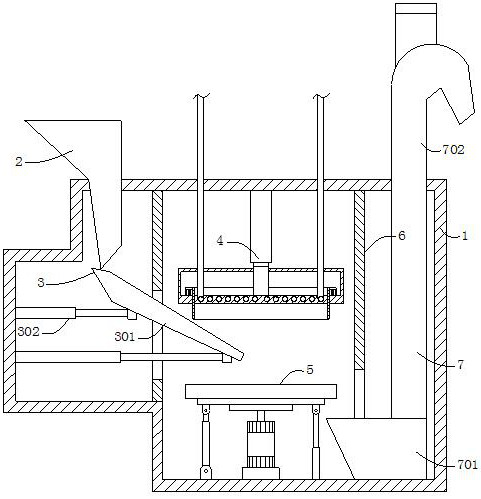
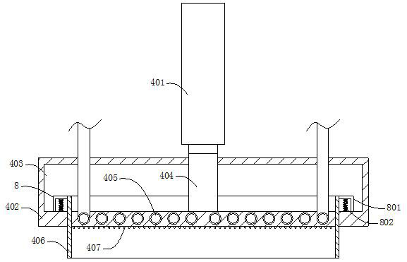
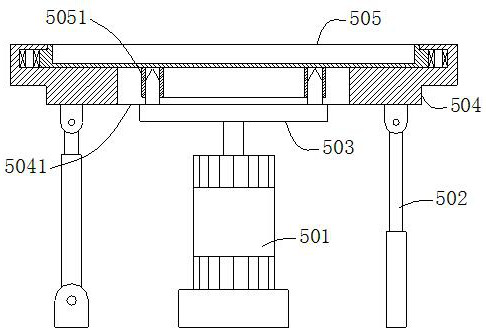
[0032] Example: such as figure 1 , figure 2 , image 3 , Figure 4 , Figure 5 and Figure 6 As shown, a blast furnace slag recycling device of the present invention includes a box body 1, and the inner cavity of the box body 1 is divided into a first zone, a second zone and a third zone in turn by two vertical partitions 6, The top of the first zone is fixedly embedded with a feed hopper 2, the middle of the first zone is equipped with a material guide mechanism 3 for conducting slag, and the top and bottom of the second zone are respectively equipped with a waste heat recovery mechanism 4 and a storage and dumping mechanism 5. The waste heat recovery mechanism 4 is arranged opposite to the accommodating and dumping mechanism 5. The waste heat recovery mechanism 4 includes a base block 402. The bottom of the base block 402 is interspersed with a limiting cylinder 406. The sides of the limiting cylinder 406 are equidistantly arranged with four Force mechanism 8, and a di...


PUM


Abstract

The blast furnace slag recycling device comprises a box body, an inner cavity of the box body is sequentially divided into a first area, a second area and a third area through two vertically-arranged partition plates, a feeding hopper is fixedly embedded in the top of the first area, and a material guiding mechanism used for guiding slag is arranged in the middle of the first area; the top and the bottom of the second area are provided with a waste heat recovery mechanism and a containing and dumping mechanism correspondingly, and the waste heat recovery mechanism and the containing and dumping mechanism are oppositely arranged. According to the invention, the waste heat recovery mechanism is matched with the accommodating and dumping mechanism to crush the slag, and waste heat recovery is carried out on the crushed slag; the slag is crushed and is uniformly laid in the placing disc, so that on one hand, efficient waste heat recovery is realized, and on the other hand, follow-up procedure treatment on the slag is facilitated; in addition, the mode that the waste heat recovery mechanism serves as a good heat conductor to make contact with the molten slag to achieve waste heat recovery is more efficient compared with the waste heat recovery mode that a conveying belt is adopted and air is spaced.

Description

technical field [0001] The invention relates to a waste heat recovery system, in particular to a blast furnace slag recycling device. Background technique [0002] Patent 1: According to the Chinese invention patent (application number: CN202010376963.7), "a high-temperature slag and waste heat recovery and processing device", including a heat recovery device and a slag processing device, and the two are connected to each other. The present invention arranges a heat recovery device and a slag processing device and connects them to each other, so that the waste heat utilization rate of the high-temperature slag is improved, and the heat loss of the slag in the transmission process is reduced; In the device, a nearly closed space is formed by setting the material transfer box, so that the slag can be kept warm during the transmission process, and the heat loss of the slag can be slowed down; It can be opened and flattened to accelerate the spread of slag in the material trans...

Claims


Application Information

Patent Timeline
Patent Type & Authority Applications(China)
IPC IPC(8): C21B3/06
CPCY02P10/20Y02W30/50Y02P10/25
Inventor 刘彦波韩西海刘腾飞韩旭
Owner 中环正奇科技有限公司
Learn More