Multifunctional mobile phone wireless charging device

A mobile phone wireless charging and wireless charger technology, which is applied in the direction of circuit devices, battery circuit devices, collectors, etc., can solve the problems of poor heat dissipation of wireless charging brackets, limited use occasions, and inability to dissipate heat in time to achieve convenient connection and fixation The effect of wireless charger structure, improved heat dissipation, and novel overall structure

Inactive Publication Date: 2020-05-05
陈文征
View PDF0 Cites 0 Cited by
  • Summary
  • Abstract
  • Description
  • Claims
  • Application Information

AI Technical Summary

Problems solved by technology

[0003] (1) During wireless charging, both the mobile phone and the wireless charger will generate a large amount of heat, but the wireless charging bracket carrying the mobile phone and the wireless charger has poor heat dissipation effect, which affects the charging effect of the overall wireless charging device;
[0004] (2) The existing wireless charging bracket has a single angle of use and cannot take into account multiple usage scenarios. Most of them are placed flat, which is not convenient for viewing mobile phones. The use occasions are limited, which limits its scope of use;
[0005] (3) The usage scenarios supported by the current wireless chargers are relatively single, that is, they can only support horizontal charging or only stand charging; moreover, a small number of them can support both standing charging and vertical wireless chargers. Complex structure and high cost;
[0006] (4) The current wireless charger, due to high heat generation and small size, is in a closed structure, which is inconvenient to dissipate heat, which will make temperature control difficult to achieve. Excessively high temperature cannot dissipate heat in time, which will reduce the performance of the wireless charger. service life

Method used


Image

  • Multifunctional mobile phone wireless charging device
  • Multifunctional mobile phone wireless charging device
  • Multifunctional mobile phone wireless charging device

Examples


Embodiment Construction

[0038] The present invention will be further described below in conjunction with the accompanying drawings.

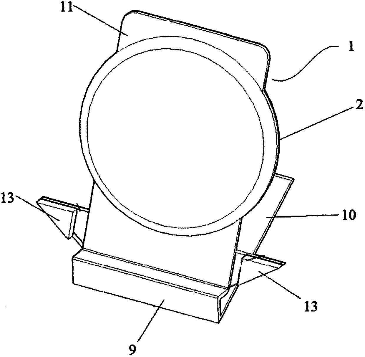
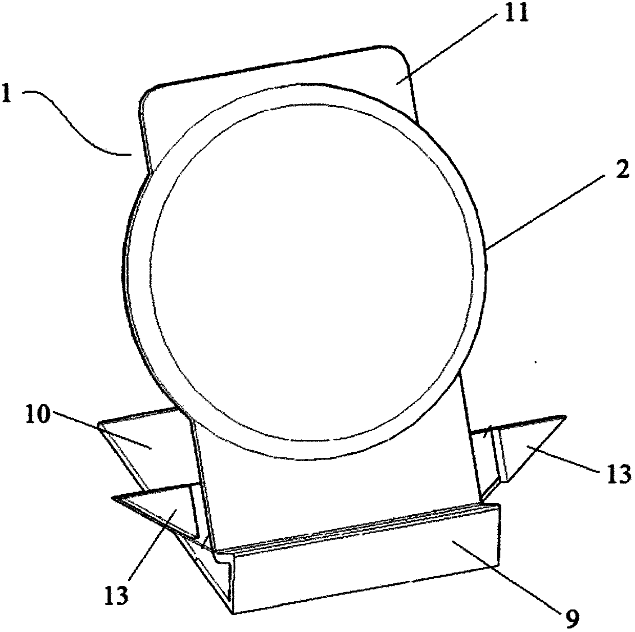
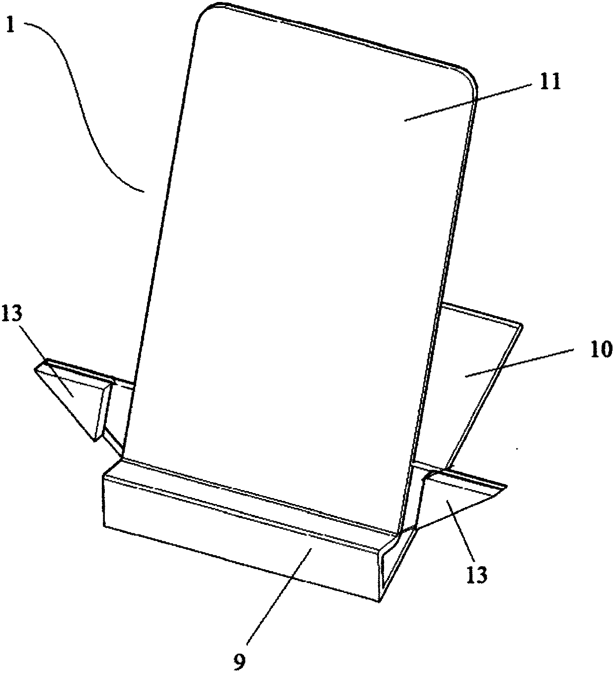
[0039] Such as figure 1 and figure 2 As shown, the multifunctional mobile phone wireless charging device of the present invention includes a charging support bracket 1 and a wireless charger structure 2,

[0040] The wireless charger structure 2 includes a front cover 3, a charging circuit board 4, a heat dissipation metal plate 5 and an elastic clamping structure 6,

[0041] Such as Figure 5 As shown, the charging circuit board 4, the heat dissipation metal plate 5 and the elastic clamping structure 6 are installed inside the front end cover 3, and one way is that the charging circuit board 4, the heat dissipation metal plate 5 and the elastic clamping structure 6 are sequentially arranged from front to back Installed inside the front end cover 3, the charging coil 7 is installed on the charging circuit board 4, and the rear side of the charging circuit board 4 a...


PUM


Abstract

The invention discloses a multifunctional mobile phone wireless charging device, which comprises a charging supporting support and a wireless charger structure. The wireless charger structure comprises a front end cover, a charging circuit board, a charging coil, a heat dissipation metal disc and an elastic clamping structure. The charging circuit board, the charging coil, the heat dissipation metal disc and the elastic clamping structure are installed in the front end cover. The rear side of the charging coil is clung to the heat dissipation metal disc; a narrow slit used for heat dissipationor clamping exists between the heat dissipation metal disc and the elastic clamping structure. The charging supporting support comprises a supporting base, the bottom side edge of the supporting basehorizontally extends towards one side to form a horizontal supporting piece, the upper side edge of the supporting base obliquely and upwards extends to form an oblique supporting connecting piece, the oblique supporting connecting piece penetrates through the narrow slit, and the charging supporting support and the wireless charger structure are fixedly installed in an inserted mode. The deviceis multifunctional, novel in structure and ingenious in conception, and has a good application prospect.

Description

technical field [0001] The invention relates to the technical field of wireless charging, in particular to a wireless charging device for a multifunctional mobile phone. Background technique [0002] With the continuous advancement of the scientific level, the current wireless charging function of mobile phones (or other handheld electronic products) is in the rising period of market recognition, and its convenient use is gradually being accepted. A mobile phone wireless charging device includes a wireless charging stand for placing the mobile phone and a wireless charger for charging the mobile phone. Currently, this type of wireless charging device on the market has the following disadvantages: [0003] (1) During wireless charging, both the mobile phone and the wireless charger will generate a large amount of heat, but the wireless charging bracket carrying the mobile phone and the wireless charger has poor heat dissipation effect, which affects the charging effect of th...

Claims


Application Information

Patent Timeline
IPC IPC(8): H02J7/00H05K7/20
CPCH02J7/0044H05K7/2039
Inventor 陈文征
Owner 陈文征
Why Eureka
Try Eureka