Prediction method for video compression

A prediction method and video compression technology, applied in the fields of digital video signal modification, image communication, electrical components, etc., can solve problems such as poor correlation, reduction of theoretical limit entropy, affecting the quality of prediction modules, etc., to achieve improved accuracy, good deviation correction effect, Optimizing the performance of forecast performance

Inactive Publication Date: 2020-05-05
XIAN CREATION KEJI CO LTD
View PDF0 Cites 0 Cited by
  • Summary
  • Abstract
  • Description
  • Claims
  • Application Information

AI Technical Summary

Problems solved by technology

However, when the texture of the image to be compressed is complex and changeable, the correlation is often poor when predicting the complex texture area of ​​the image to be compressed, and the predi

Method used


Image

  • Prediction method for video compression
  • Prediction method for video compression
  • Prediction method for video compression

Examples


Embodiment 1

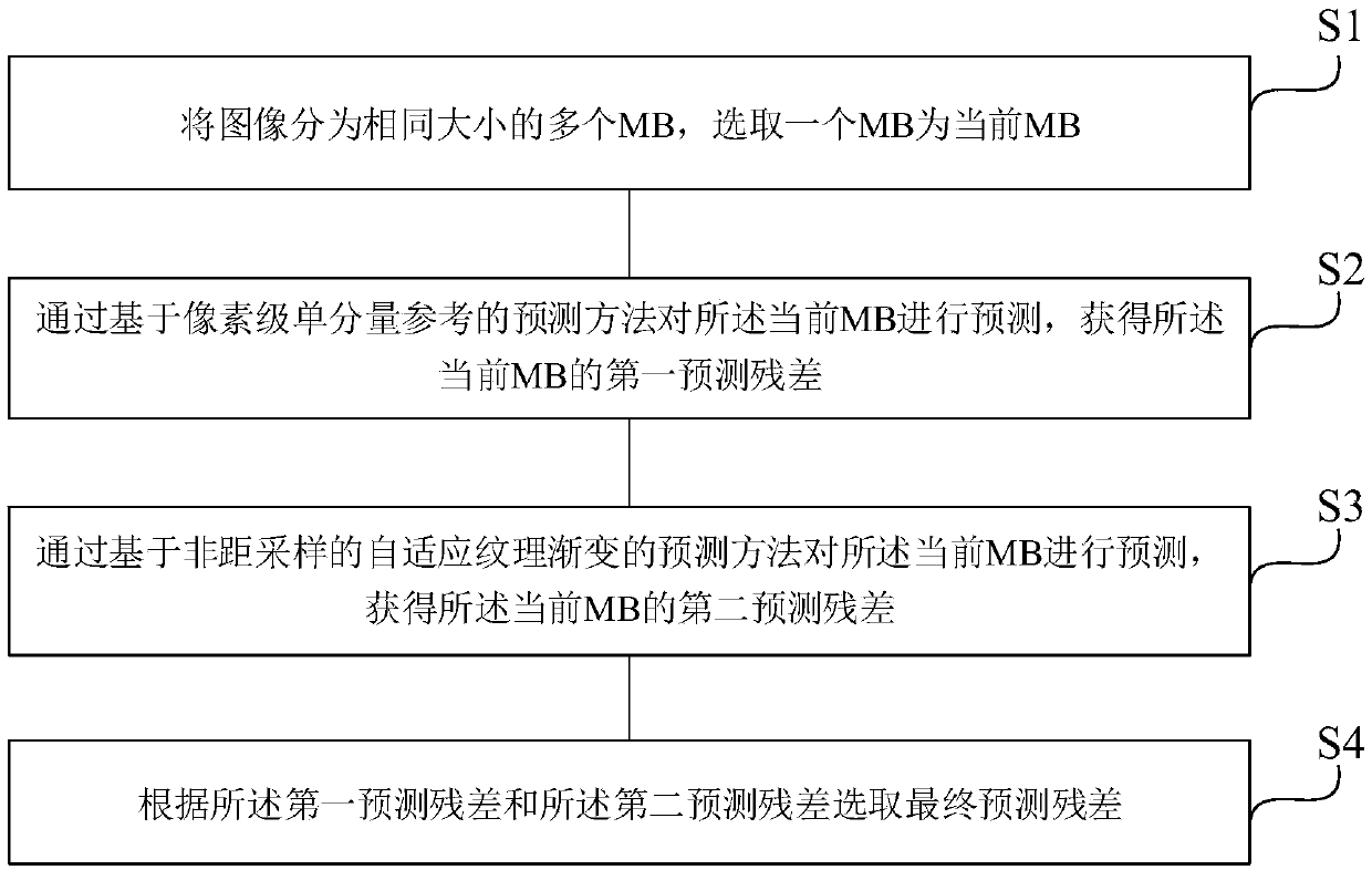
[0058] See figure 1 , figure 1 It is a flowchart of a prediction method in video compression provided by an embodiment of the present invention. The prediction method in the video compression of embodiment comprises:

[0059] S1: Divide the image into multiple MBs of the same size, and select one MB as the current MB;

[0060] S2: Predict the multiple MBs by using a prediction method based on a pixel-level single-component reference, and obtain first prediction residuals of the multiple MBs;

[0061] S3: Predict the multiple MBs by using a non-distance sampling based adaptive texture gradient prediction method to obtain second prediction residuals of the multiple MBs;

[0062] S4: Select a final prediction residual according to the first prediction residual and the second prediction residual.

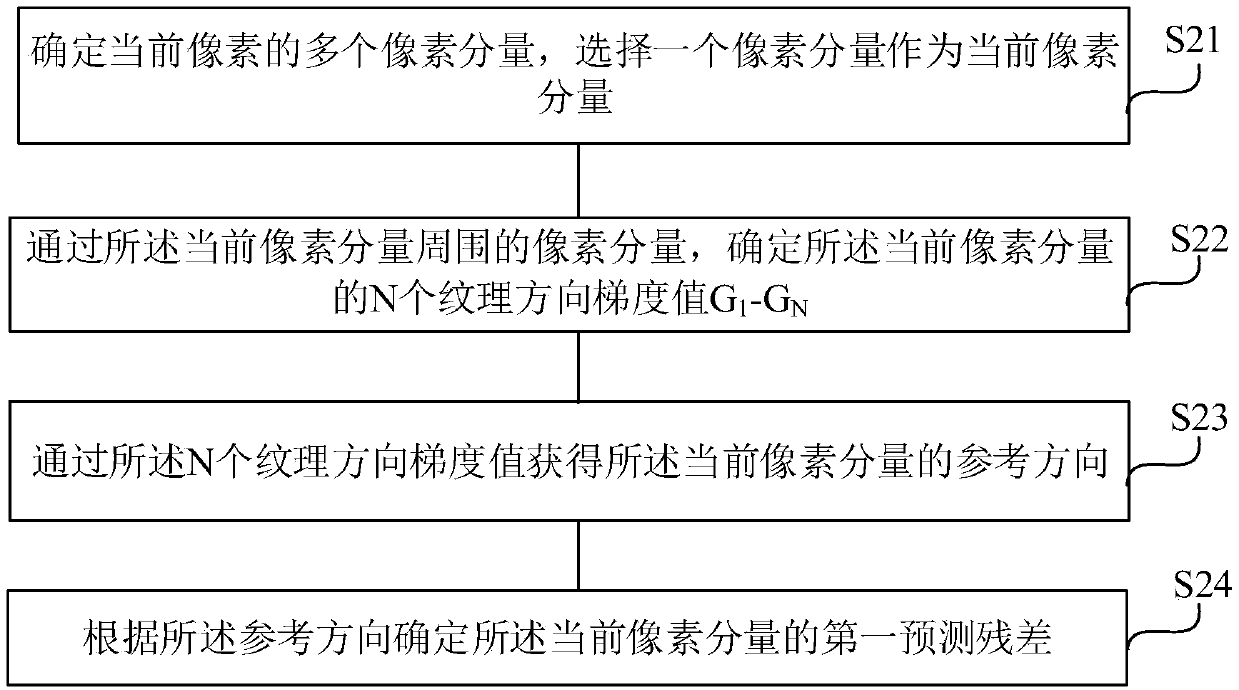
[0063] Further, see figure 2 , figure 2 It is a flow chart of a prediction method based on pixel-level single-component reference provided by an embodiment of the present inventio...

Embodiment 2

[0088] See Image 6 , Image 6 It is a flowchart of a non-distance sampling based adaptive texture gradient prediction method provided by an embodiment of the present invention. In this embodiment, the prediction method of adaptive texture gradient based on non-distance sampling includes the following steps:

[0089] S31: Determine the size of the current MB as n*1, where n is a positive integer;

[0090] S32: Select T non-equidistant sampling methods to sample pixels in the current MB, where T is an integer greater than 1;

[0091] S33: Select M prediction methods to predict the current MB in each sampling method;

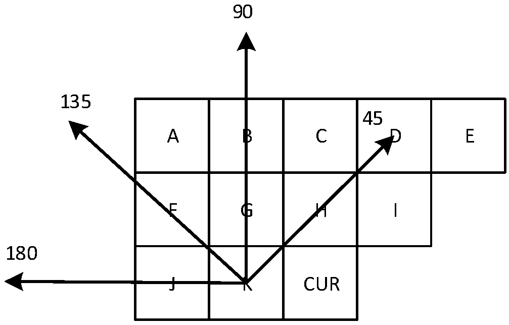
[0092] Preferably, the prediction method is an angle prediction method, including 45-degree texture prediction, 90-degree texture prediction and 135-degree texture prediction.

[0093] S34: Calculate respectively the prediction residual of the current MB in each sampling mode;

[0094] S35: Select a final sampling mode and a final prediction mode of the curre...

Embodiment 3

[0107] See Figure 7 with Figure 8 , Figure 7 A schematic diagram of a sampling method of an adaptive texture gradient prediction method provided by an embodiment of the present invention; Figure 8 It is a schematic diagram of an adaptive texture gradient prediction method provided by an embodiment of the present invention. On the basis of the second embodiment, this embodiment further exemplarily describes the prediction method of adaptive texture gradient based on non-distance sampling.

[0108] Specifically, the prediction method of adaptive texture gradient based on non-distance sampling includes the following steps:

[0109] Step 1. Define the MB size

[0110] Define the size of MB as m*n pixel components, where m≥1, n≥1;

[0111] Preferably, the size of MB can be defined as 8*1 pixels, 16*1 pixels, 32*1 pixels, and 64*1 pixels; this embodiment uses 16*1 pixels as an example for illustration, other sizes The MB is the same. The pixels in the MB are arranged sequ...


PUM


Abstract

The invention relates to a prediction method for video compression, and the method comprises the steps: dividing an image into a plurality of MBs with the same size, and selecting one MB as a currentMB; predicting the current MB through a prediction method based on pixel-level single-component reference to obtain a first prediction residual error of the current MB; predicting the current MB through an adaptive texture gradient prediction method based on non-distance sampling to obtain a second prediction residual error of the current MB; and selecting a final prediction residual error according to the first prediction residual error and the second prediction residual error. According to the method, the optimal prediction method is selected from the prediction method based on pixel-level single-component reference and the prediction method based on non-distance sampling adaptive texture gradient through a prediction selection algorithm, and the prediction effect of a complex texture image can be further optimized.

Description

technical field [0001] The invention belongs to the technical field of video compression, and in particular relates to a prediction method for video compression. Background technique [0002] As people's demand for video quality continues to increase, image resolution, as an important feature of video quality, has transitioned from 720p and 1080p to the current 4K video resolution, and the corresponding video compression standard has also transitioned from H.264 to H. 265. For video processing chips, the multiple increase in resolution will not only cause a substantial increase in chip area cost, but also have a great impact on bus bandwidth and power consumption. [0003] In order to overcome this problem, the bandwidth compression technology applied in the chip is proposed. The goal of on-chip bandwidth compression is to increase the compression factor as much as possible with a smaller logic area cost. On-chip compression is divided into two types: lossy compression an...

Claims


Application Information

Patent Timeline
IPC IPC(8): H04N19/50H04N19/52H04N19/42H04N19/70
CPCH04N19/42H04N19/50H04N19/52H04N19/70
Inventor 冉文方李雯
Owner XIAN CREATION KEJI CO LTD
Why Eureka
Try Eureka