Supercharge Your Innovation With Domain-Expert AI Agents!

Three-spindle numerical control machine tool

A technology of CNC machine tools and spindle motors, applied in the field of machine tools, can solve problems such as inability to link, and achieve the effect of improving production efficiency

Pending Publication Date: 2020-05-08
龙口市蓝牙数控装备有限公司
View PDF1 Cites 0 Cited by
  • Summary
  • Abstract
  • Description
  • Claims
  • Application Information

AI Technical Summary

Problems solved by technology

However, the three processing equipment are controlled by their own CNC devices, which is equivalent to three machine tools sharing one bed, which only saves space and is easy to operate. The three processing equipment cannot be linked together, so it is not a three-spindle CNC machine tool in the true sense.

Method used


Image

  • Three-spindle numerical control machine tool
  • Three-spindle numerical control machine tool

Examples


Embodiment 1

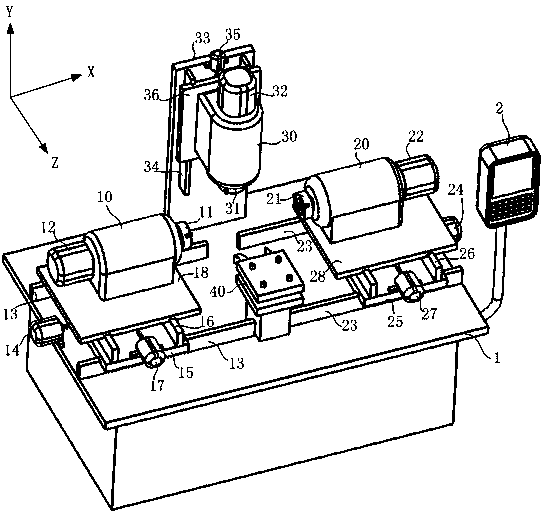
[0018] Embodiment 1, as shown in the figure, a three-spindle CNC machine tool includes a machine platform 1 and a numerical control system 2, and a first spindle box 10 capable of moving in the X and Z directions is installed on the left side of the machine platform 1 , the second headstock 20 capable of moving in the X and Z directions is installed on the right side of the machine platform 1, and the third headstock 30 capable of moving in the Y direction is installed on the rear side of the middle part of the machine platform 1 A tool rest 40 is fixed on the front side of the middle part of the machine table 1, and the first main shaft, the second main shaft and the third main shaft are respectively pivoted in the first main headstock 10, the second main headstock 20 and the third main headstock 30. Main shaft, the right end of the first main shaft extends out of the first headstock 10 and connects to the first holder 11, and the left end of the second main shaft extends out ...

Embodiment 2

[0036] Embodiment 2, other is the same as Embodiment 1, the difference is that the first spindle motor 12 is located on one side of the first spindle box 10, and the motor shaft of the first spindle motor 12 is fixedly connected to the driving synchronous pulley , the first main shaft is fixedly connected to the driven synchronous pulley, and a synchronous belt is set on the driving synchronous pulley and the driven synchronous pulley; the second main shaft motor 22 is located on one side of the second main shaft box 20, so The motor shaft of the second main shaft motor 22 is fixedly connected to the driving synchronous pulley, the first main shaft is fixed to the driven synchronous pulley, and a synchronous belt is sleeved on the driving synchronous pulley and the driven synchronous pulley; the third main shaft The motor 32 is located on one side of the third spindle box 30, the motor shaft of the third spindle motor 32 is fixed to the driving synchronous pulley, the first mai...


PUM


Abstract

The invention relates to a machine tool, in particular to a three-spindle numerical control machine tool. The three-spindle numerical control machine tool comprises a machine table and a numerical control system, wherein a first spindle box capable of moving in the X direction and the Z direction is arranged on the left side of the machine table; a second spindle box capable of moving in the X direction and the Z direction is arranged on the right side of the machine table; a third spindle box capable of moving in the Y direction is arranged on the rear side of the middle of the machine table;a tool rest is fixedly arranged on the front side of the middle of the machine table; a first spindle, a second spindle and a third spindle are pivoted in the first spindle box, the second spindle box and the third spindle box correspondingly; the right end of the first spindle extends out of the first spindle box to be connected with a first clamper; the left end of the second spindle extends out of the second spindle box to be connected with a second clamper; the lower end of the third spindle extends out of the third spindle box to be connected with a third clamper; and the first clamper,the second clamper and the third clamper can clamp workpieces or tools. Compared with the prior art, the three-spindle numerical control machine tool can achieve almost all machining processes, and the production efficiency can be greatly improved through five-axis linkage.

Description

technical field [0001] The invention relates to machine tools, in particular to a three-spindle numerical control machine tool. Background technique [0002] The Chinese utility model patent with the publication number CN203679286U discloses a vertical three-spindle CNC lathe, including a bed whose cross-section is "U"-shaped, and three processing equipment are installed on the bed. The three processing equipment are respectively installed on the left side, right side and rear side of the bed; each processing equipment includes a spindle box, a spindle, a tool holder, a driving device and a numerical control device, and the spindle box is installed under the bed, A clamping device is installed at one end of the main shaft, a horizontal moving device is installed at the bottom of the tool holder, and a vertical moving device is installed at the bottom of the tool holder. However, the three processing equipment are controlled by their own CNC devices, which is equivalent to t...

Claims


Application Information

Patent Timeline
IPC IPC(8): B23Q39/02
CPCB23Q39/02B23Q2039/006
Inventor 王建斌王建鹏王嘉轩
Owner 龙口市蓝牙数控装备有限公司
Features
  • R&D
  • Intellectual Property
  • Life Sciences
  • Materials
  • Tech Scout
  • Unparalleled Data Quality
  • Higher Quality Content
  • 60% Fewer Hallucinations
Learn More