
Wooden table leg automatic rotary drilling equipment

A technology of automatic rotating and punching equipment, applied in wood processing appliances, stationary drilling machines, bark area / debris / dust / waste removal and other directions, can solve the problems of inconvenient collection of debris, dangerous processing, time-consuming and laborious, etc. Achieve the effect of saving manpower, maintaining accuracy, and avoiding industrial accidents

Inactive Publication Date: 2020-05-08
肖鹏
View PDF8 Cites 0 Cited by
  • Summary
  • Abstract
  • Description
  • Claims
  • Application Information

AI Technical Summary

Problems solved by technology

[0004] In order to overcome the shortcomings of dangerous processing, unstable precision, time-consuming and laborious, and inconvenient collection of debris, the technical problem to be solved is: to provide a wooden table leg automatic that is safe, reliable, stable in precision, time-saving and labor-saving, and can collect generated debris. Rotary punching equipment

Method used


Image

  • Wooden table leg automatic rotary drilling equipment
  • Wooden table leg automatic rotary drilling equipment
  • Wooden table leg automatic rotary drilling equipment

Examples


Embodiment 1

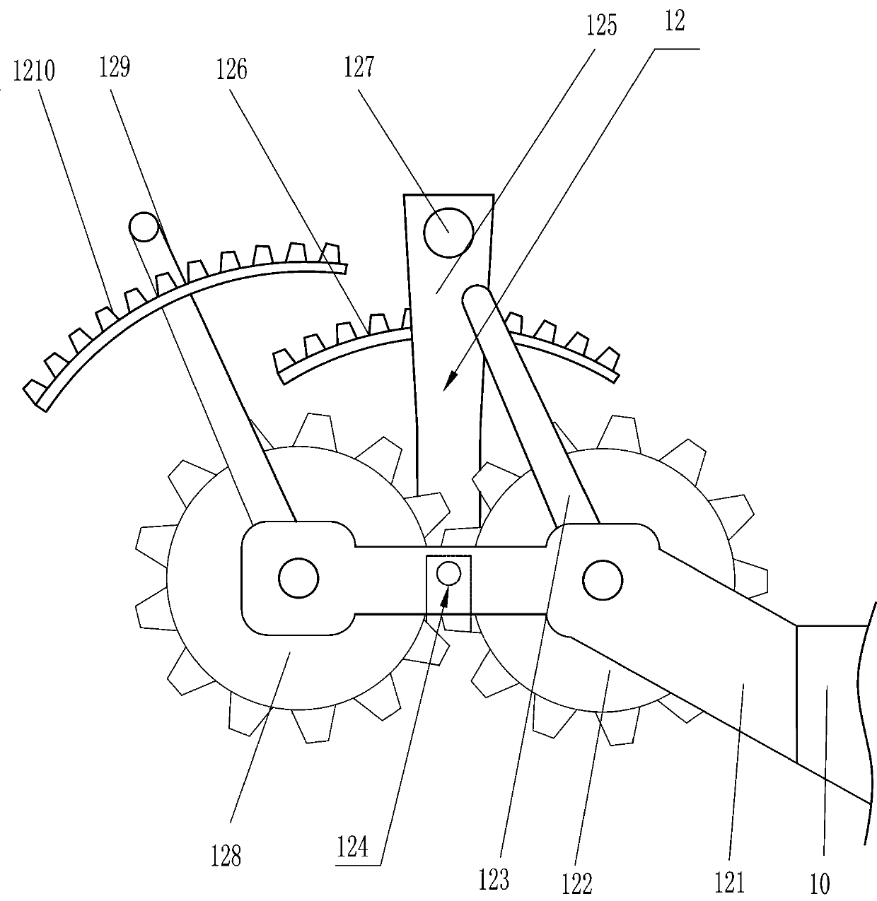
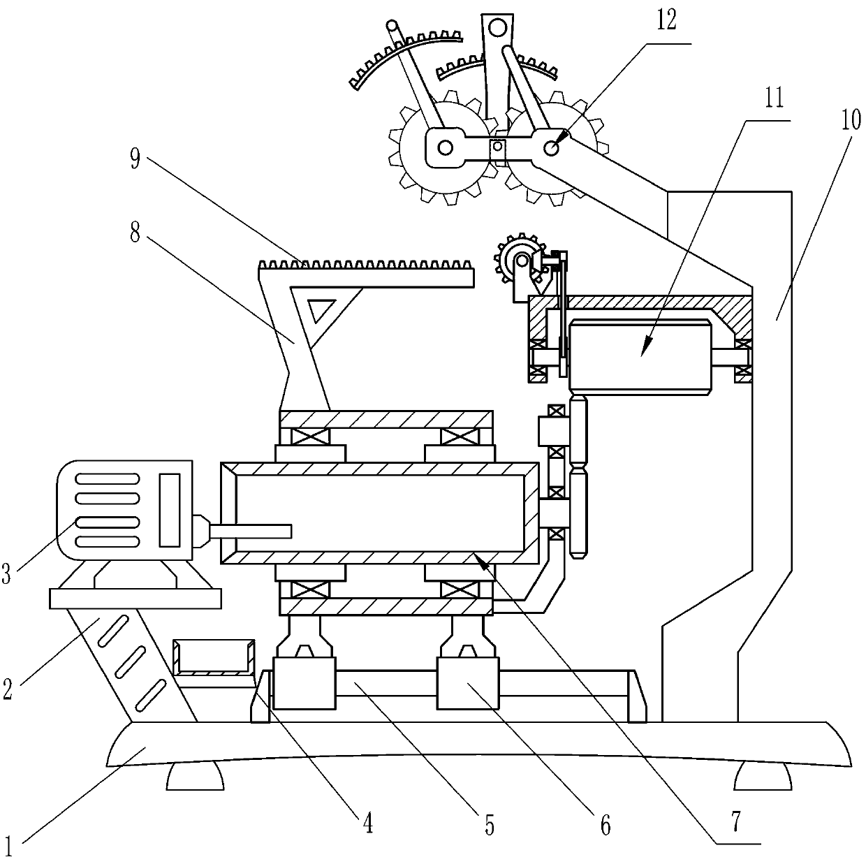
[0022] An automatic rotary punching device for wooden table legs, such as figure 1 As shown, it includes a mounting seat 1, a first support plate 2, a drilling machine 3, a support 4, a guide rail 5, a guide sleeve 6, a rolling device 7, a first bracket 8, a spur rack 9, a second bracket 10, The rotating device 11 and the power device 12 are specifically:

[0023] The left side of the upper part of the mounting seat 1 is provided with a first support plate 2, the upper part of the first support plate 2 is equipped with a drilling machine 3, the middle of the upper part of the mounting seat 1 is symmetrically provided with a support 4, and a guide rail 5 is provided between the support 4, and the guide rail There are two guide sleeves 6 in the sliding type on 5, the upper part of the guide sleeve 6 is provided with a rolling device 7, the upper part of the rolling device 7 is provided with a first bracket 8, the upper part of the first bracket 8 is provided with a straight rack...

Embodiment 2

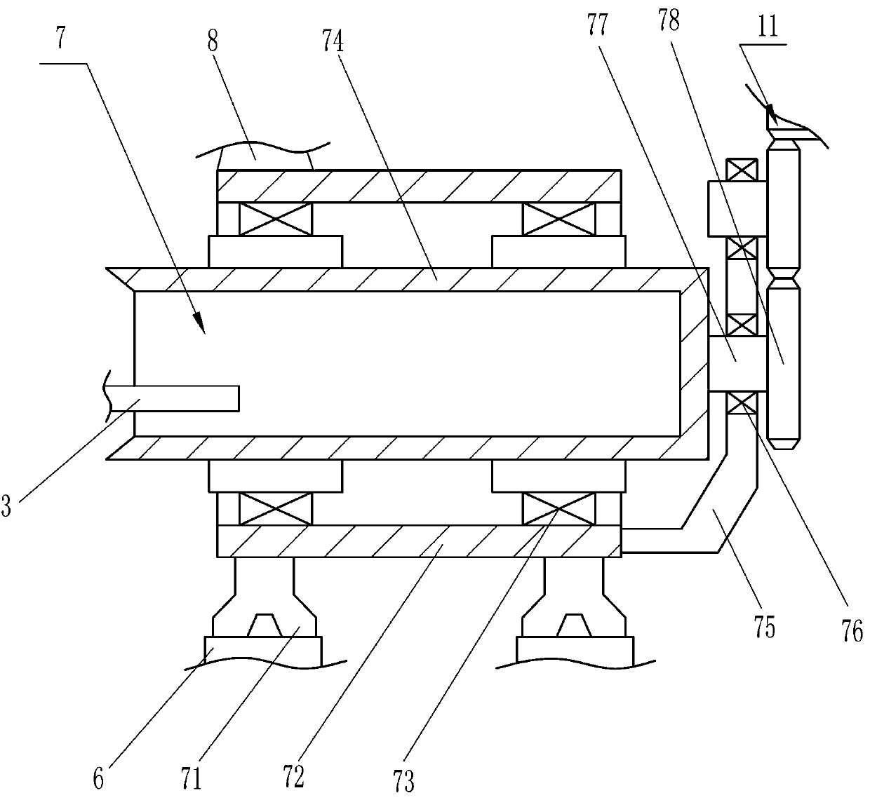
[0026] On the basis of Example 1, such as Figure 2-6 As shown, the rolling device 7 includes a support block 71, an outer frame body 72, a first bearing seat 73, a raw material placement box 74, a connecting frame 75, a second bearing seat 76, a first rotating rod 77 and a first gear 78, specifically for:

[0027] The upper part of the guide sleeve 6 is provided with a supporting block 71, the upper part of the supporting block 71 is provided with an outer frame body 72, the left side of the upper part of the outer frame body 72 is connected with the first bracket 8, and the inner side of the outer frame body 72 is symmetrically equipped with a first bearing seat 73, The first bearing seat 73 is provided with a raw material placement box 74, and the right side of the outer frame body 72 bottom is provided with a connecting frame 75, and two groups of second bearing blocks 76 are installed vertically on the upper part of the right side of the connecting frame 75, and the secon...


PUM


Abstract

The invention relates to furniture processing, in particular to wooden table leg automatic rotary drilling equipment. The technical problem to be solved is how to provide the safe and reliable, accurate and stable, time-saving and labor-saving wooden table leg automatic rotary drilling equipment capable of collecting generated debris. The wooden table leg automatic rotary drilling equipment comprises a mounting base, a first support plate, a drilling machine, a support, etc.; and a first support plate is arranged on the left side of the upper part of the mounting base. According to the woodentable leg automatic rotary drilling equipment, a worker is safer in the processing process through a processing mode of automatic carry, retreat and rotation, and occurrence of industrial accidents isavoided; and on the other hand, the accuracy of wooden table leg processing is maintained by a way of mechanical control, and an automatic production mode saves manpower, avoids the worker holding heavy wood table legs for a long time, and improves the working efficiency of processing.

Description

technical field [0001] The invention relates to furniture processing, in particular to an automatic rotary punching device for wooden table legs. Background technique [0002] At present, when people punch holes in wooden table legs, the drilling machine is usually fixed on the desktop, and the worker holds the wooden table legs to be processed on the desktop, and then pushes the wooden table legs forward to start drilling. The disadvantage is that the workers push the wooden table legs when the drilling machine is working, which may easily cause industrial accidents such as bruising hands, and when drilling, the workers manually adjust the position of the drilling holes to easily cause errors, and it is difficult to maintain the accuracy of the drilling On the other hand, workers holding heavy wooden table legs for a long time will cause muscle fatigue and soreness in the hands, which will affect the long-term efficient work of the workers. In addition, the debris generated...

Claims


Application Information

Patent Timeline
IPC IPC(8): B27C3/02B27G3/00
CPCB27C3/02B27G3/00
Inventor 肖鹏
Owner 肖鹏
Features
  • Generate Ideas
  • Intellectual Property
  • Life Sciences
  • Materials
  • Tech Scout
  • Unparalleled Data Quality
  • Higher Quality Content
  • 60% Fewer Hallucinations
Learn More