Screw and injection molding machine

A technology of screw and thread segment, which is applied in the field of injection molding machines, to achieve the effect of shortening the production cycle, shortening the research and development cycle, and avoiding waste of resources

Inactive Publication Date: 2020-05-08
ZHUHAI GREE INTELLIGENT EQUIP CO LTD +1
View PDF3 Cites 1 Cited by
  • Summary
  • Abstract
  • Description
  • Claims
  • Application Information

AI Technical Summary

Problems solved by technology

[0004] The main purpose of the present invention is to provide a screw and an injection molding machine to solve the problem that the injection molding machine in the prior art needs to replace the entire screw when replacing the screw

Method used


Image

  • Screw and injection molding machine
  • Screw and injection molding machine
  • Screw and injection molding machine

Examples


Embodiment Construction

[0022] The following will clearly and completely describe the technical solutions in the embodiments of the present invention with reference to the accompanying drawings in the embodiments of the present invention. Obviously, the described embodiments are only some of the embodiments of the present invention, not all of them. The following description of at least one exemplary embodiment is merely illustrative in nature and in no way taken as limiting the invention, its application or uses. Based on the embodiments of the present invention, all other embodiments obtained by persons of ordinary skill in the art without creative efforts fall within the protection scope of the present invention.

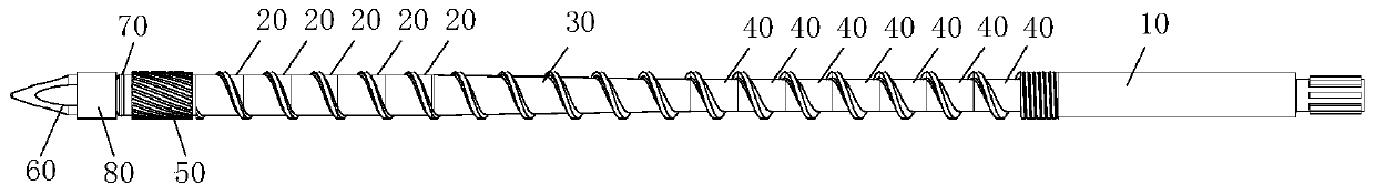
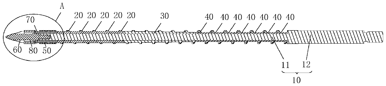
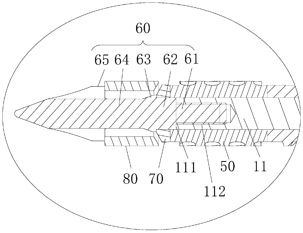
[0023] In order to solve the problem that the entire screw needs to be replaced when replacing the screw in the injection molding machine in the prior art, the present invention provides a screw and an injection molding machine.

[0024] Such as Figure 1 to Figure 3 As shown, the scre...


PUM


Abstract

The invention provides a screw and an injection molding machine. The screw comprises a connecting shaft, a homogenizing section, a compressing section and a feeding section. The homogenizing section,the compressing section and the feeding section are sequentially arranged on the connecting shaft in a sleeving manner. The homogenizing section and the feeding section are of equal-diameter structures, the diameter of the homogenizing section is larger than that of the feeding section, the diameter of the compressing section is gradually reduced from the homogenizing section to the feeding section, the diameter of the first end, close to the homogenizing section, of the compressing section and the diameter of the homogenizing section are equal, and the diameter of the second end, close to thehomogenizing section, of the compressing section and the diameter of the feeding section are equal. According to the technical scheme, the problem that when a screw of an injection molding machine inthe prior art is replaced, it is needed to replace the whole screw is solved.

Description

technical field [0001] The invention relates to the technical field of injection molding machines, in particular to a screw and an injection molding machine. Background technique [0002] The screw is one of the key components of the injection molding machine. When the injection molding machine is working, the granular or powdery plastic is first added into the barrel, and the granular or powdery plastic is plasticized by rotating the screw relative to the barrel and heating the outer wall of the barrel. Become the plastic in the molten state, and then use the screw to inject the plasticized plastic in the molten state into the cavity of the molding mold at a higher pressure and faster speed. The structure of the screw will affect the effect of the plastic. For different types of plastics, different screw structures are required, and the screw is easy to wear during use. [0003] However, the screw in the related art adopts an integrated design. When it is necessary to chan...

Claims


Application Information

Patent Timeline
Patent Type & Authority Applications(China)
IPC IPC(8): B29C45/60
CPCB29C45/60
Inventor 林海城莫玉麟卢全武赵永政张济鹏杨桃甲张天翼张秀峰
Owner ZHUHAI GREE INTELLIGENT EQUIP CO LTD
Why Eureka
Try Eureka