
Steel billet feeding device in cutting area

A cutting area and steel billet technology, applied in the field of billet feeding device in the cutting area, can solve the problems of wasting manpower and material resources, poor working stability, complex structure, etc., and achieve the effects of convenient operation, increased bearing life, and smooth movement

Pending Publication Date: 2020-05-08
中重科技(天津)股份有限公司
View PDF0 Cites 0 Cited by
  • Summary
  • Abstract
  • Description
  • Claims
  • Application Information

AI Technical Summary

Problems solved by technology

However, in the prior art, a hydraulically driven feeding device is commonly used, which requires a separate hydraulic station and other equipment, with complex structure, slow speed, poor working stability, and waste of manpower and material resources

Method used


Image

  • Steel billet feeding device in cutting area
  • Steel billet feeding device in cutting area
  • Steel billet feeding device in cutting area

Examples


Embodiment Construction

[0041] It should be noted that, in the case of no conflict, the embodiments of the present invention and the features in the embodiments can be combined with each other.

[0042]In describing the present invention, it should be understood that the terms "center", "longitudinal", "transverse", "upper", "lower", "front", "rear", "left", "right", " The orientations or positional relationships indicated by "vertical", "horizontal", "top", "bottom", "inner" and "outer" are based on the orientations or positional relationships shown in the drawings, and are only for the convenience of describing the present invention and Simplified descriptions, rather than indicating or implying that the device or element referred to must have a particular orientation, be constructed and operate in a particular orientation, and thus should not be construed as limiting the invention. In addition, the terms "first", "second", etc. are used for descriptive purposes only, and should not be understood a...


PUM


Abstract

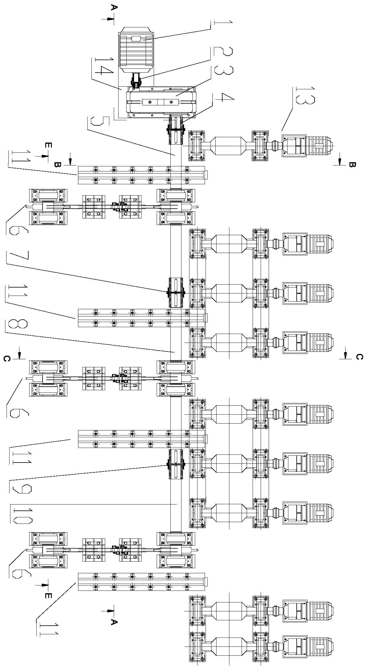
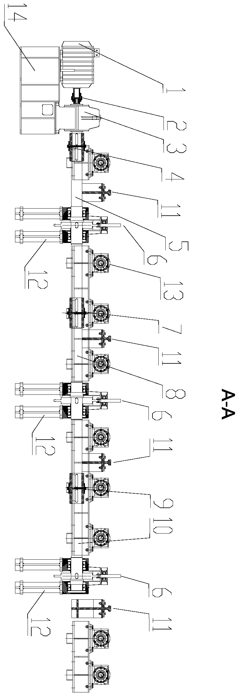
The invention provides a steel billet feeding device in a cutting area. The steel billet feeding device comprises a main motor, a speed reducer, a transmission shaft, a material stirring mechanism, asupporting beam and a conveying roller mechanism, wherein chain wheels are arranged in the material stirring mechanism, the chain wheels are connected in a matched mode through long-pitch conveying chains, stopping blocks are fixed on the long-pitch conveying chains, roller bearings are arranged on the two sides of the stopping blocks in a staggered mode, a main motor drives the chain wheels to rotate, the chain wheels drive the long-pitch conveying chains to rotate, the roller bearings on the stopping blocks move along the inner side of guiding rails, the stopping blocks push a steel billet to be fed, and the steel billet enters the conveying roller mechanism along the supporting beam. According to the steel billet feeding device in the cutting area, the steel billet feeding efficiency can be improved, the labor cost is reduced, the production cost is saved, and the production efficiency is improved.

Description

technical field [0001] The invention belongs to the field of billet feeding, in particular to a billet feeding device in a cutting area. Background technique [0002] In recent years, with the rapid development of my country's economy, people's consumption level has been continuously improved, which has greatly promoted the vigorous development of civil construction, automobile and other industries. The government has also spared no effort to increase investment in infrastructure. As an upstream beneficiary industry, the iron and steel industry has been greatly developed, but at the same time it has put forward higher requirements for the production efficiency of the industry, and the specifications of foreign steel billets do not match the specifications of domestic rolling mills, so it is necessary to cut the steel billets purchased abroad. The cut steel billet needs to be fed to the slag removal roller table, but the slag removal area is generally a certain distance from...

Claims


Application Information

Patent Timeline
Patent Type & Authority Applications(China)
IPC IPC(8): B65G13/00B65G47/04B65G47/82
CPCB65G13/00B65G47/04B65G47/82B65G2201/0214
Inventor 王守东
Owner 中重科技(天津)股份有限公司
Learn More