
Cold dyeing device and cold dyeing process

A technology of cold dyeing and equipment, which is applied in the field of cold dyeing equipment and cold dyeing technology, which can solve the problems of slow running speed of cloth, easy sedimentation, poor effect of cloth fiber dyeing, etc., and achieve the effect of improving the effect of dyeing and speeding up the flow

Active Publication Date: 2020-05-08
浙江中纺控股集团有限公司
View PDF8 Cites 5 Cited by
  • Summary
  • Abstract
  • Description
  • Claims
  • Application Information

AI Technical Summary

Problems solved by technology

[0004] When the existing fabric cold-pile combined machine is dip-dyeing the fabric, the running speed of the fabric is slow, so that the solid matter in the dye in the flat washing tank is easy to settle to the bottom of the flat washing tank, and because the dye basically does not flow , so that the effect of the dye on the cloth fiber is poor

Method used


Image

  • Cold dyeing device and cold dyeing process
  • Cold dyeing device and cold dyeing process
  • Cold dyeing device and cold dyeing process

Examples


Embodiment 1

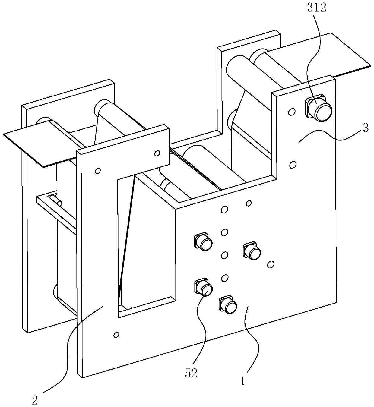
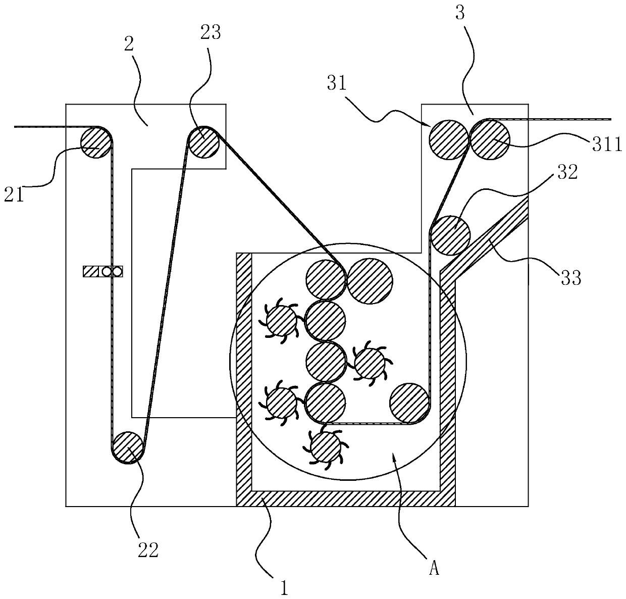
[0040]Embodiment 1: A kind of cold dyeing equipment, comprising a cold dyeing box 1, two feed racks 2 arranged on the feeding side of the cold dyeing box 1, and two output racks arranged on the side of the cold dyeing box 1 away from the feed rack 2 frame 3. The position near the top between the two feeding frames 2 is provided with a feed roller 21, and the two ends of the feed roller 21 are respectively rotatably connected to the two feed frames 2, and a guide roller 22 is arranged below the feed roller 21, and the guide roller The two ends of 22 are respectively rotatably connected on the two feeding racks 2, the axial direction of the feeding roller 21 is arranged horizontally and is parallel to the axial direction of the guide roller 22, and the side of the feeding roller 21 near the cold dyeing box 1 is provided with two Rotate the guide rollers 23 connected to the feed frame 2 respectively, the axis direction of the guide rollers 23 and the axis direction of the guide r...

Embodiment 2

[0048] Embodiment two: a kind of cold dyeing process, comprises the following steps:

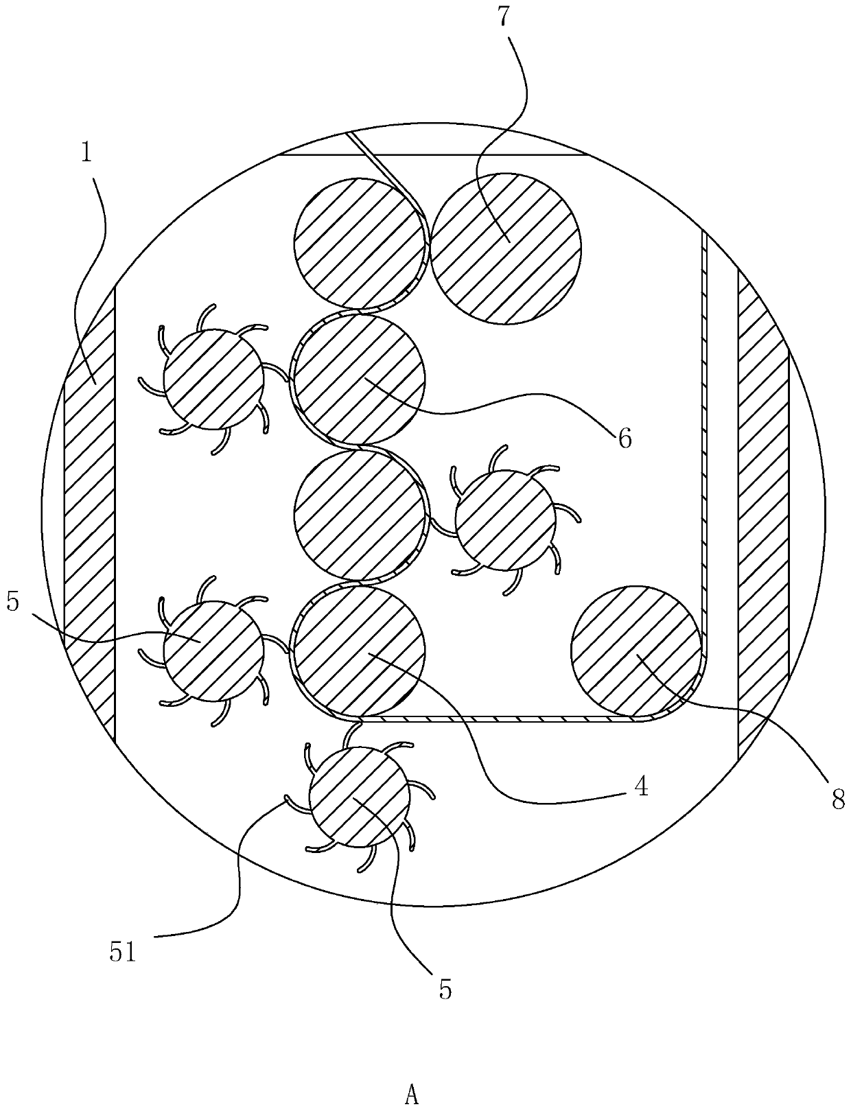
[0049] a. Configure the dye: configure the dye according to the color to be dyed, put the configured dye into the cold dyeing box 1, so that the axes of the squeeze roller 7 on the liquid surface of the dye are flush with each other;

[0050] b. Dip dyeing: pass the cloth from the top of the feed roller 21 and then pull down the cloth so that the two sides of the cloth are respectively clamped between the two spreading rollers 93 on both sides of the cloth, then the cloth is passed around the bottom of the guide roller 22, and then The cloth is bypassed from the top of the guide roller 23, then the cloth is passed between the top winding roller 6 and the squeeze roller 7, and then the cloth passes between the top winding roller 6 and the middle winding roller 6 And the cloth and the winding roller 6 in the middle are in contact with each other near the feeding frame 2, and then the cloth i...


PUM


Abstract

The invention discloses a cold dyeing device and a cold dyeing process. According to the technical scheme, the cold dyeing device comprises a cold dyeing box, two feeding frames arranged on one side of the feeding side of the cold dyeing box, and two discharging frames arranged on one side, away from the feeding frame, of the cold dyeing box; the cold dyeing process comprises the following steps of a, configuring a dye; b, carrying out dip dyeing; c, performing stacking and color fixing; e, performing washing; and e, performing drying; and driving the dye to flow through a stirring roller, sothat solid substances in the dye cannot easily settle to the bottom of a flat washing tank, driving a material shifting plate to repeatedly extrude cloth, and improving the dip dyeing effect of the dye on the cloth fibers.

Description

technical field [0001] The invention relates to the technical field of cloth dyeing, more specifically, it relates to a cold dyeing equipment and a cold dyeing process. Background technique [0002] Cold pad-batch dyeing is a new type of non-toxic dyeing method, which mainly includes three stages of dipping, stacking and water washing. Compared with traditional dyeing, cold pad-batch dyeing does not require a large amount of dyeing accelerator and does not require heating. [0003] In the prior art, the Chinese utility model patent document whose authorized announcement number is CN205347751U discloses a cloth cold-pile combined machine, which includes structures such as a cloth feeding frame, a flat washing tank, a two-roll rolling car, and a looping and falling cloth frame; Several flat washing tanks and two-roll padders are used to cold pad-batch the dyed fabric. [0004] When the existing cloth cold-pile combined machine is dip-dyeing the cloth, the running speed of th...

Claims


Application Information

Patent Timeline
IPC IPC(8): D06B3/10D06B23/20D06B17/02D06B15/02
CPCD06B3/10D06B23/20D06B17/02D06B15/02
Inventor 刘文俊
Owner 浙江中纺控股集团有限公司
Learn More