Energy storage sealing structure and dynamic sealing device for high-pressure easily vaporized medium

A sealing structure and dynamic sealing technology, which is applied to parts of pumping devices for elastic fluids, rocket engine devices, jet propulsion devices, etc., can solve problems such as unstable specific pressure, poor sealing effect, and medium leakage, and achieve Ensure the sealing effect, ensure the sealing performance, and avoid the effect of collision

Inactive Publication Date: 2020-05-08
BEIJING XINGJI RONGYAO SPACE TECH CO LTD +2
View PDF0 Cites 2 Cited by
  • Summary
  • Abstract
  • Description
  • Claims
  • Application Information

AI Technical Summary

Problems solved by technology

[0006] Therefore, the technical problem to be solved by the present invention is to overcome the defects that the high-pressure dynamic sealing device in the prior art is complicated in structure and easily fails to cause medium leakage, thereby providing an energy-storage sealing structure with a simple structure and good sealing effect and used for high-pressure Dynamic sealing device for easily vaporized medium
[0007] Another technical problem to be solved by the present invention is to overcome the defects in the prior art that the static ring is easy to collide with the moving ring after wear and tear, which affects the sealing effect
[0008] Another technical problem to be solved by the present invention is to overcome the defect that the sealing end faces of the moving ring and the static ring are unstable due to friction before and after work, resulting in poor sealing effect

Method used


Image

  • Energy storage sealing structure and dynamic sealing device for high-pressure easily vaporized medium
  • Energy storage sealing structure and dynamic sealing device for high-pressure easily vaporized medium
  • Energy storage sealing structure and dynamic sealing device for high-pressure easily vaporized medium

Examples


Embodiment Construction

[0034] The technical solutions of the present invention will be clearly and completely described below in conjunction with the accompanying drawings. Apparently, the described embodiments are some of the embodiments of the present invention, but not all of them. Based on the embodiments of the present invention, all other embodiments obtained by persons of ordinary skill in the art without making creative efforts belong to the protection scope of the present invention.

[0035] In addition, the technical features involved in the different embodiments of the present invention described below may be combined with each other as long as there is no conflict with each other.

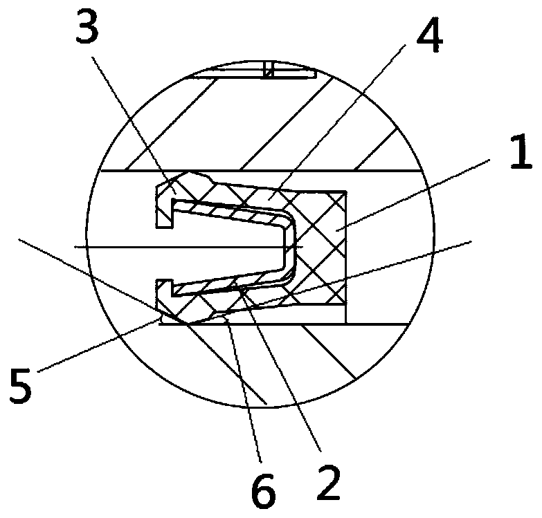
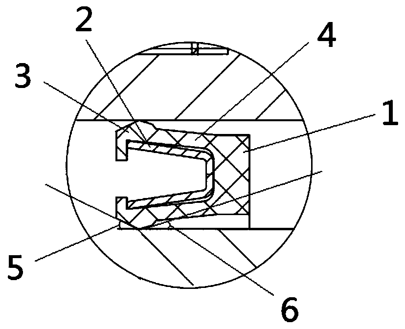
[0036] Such as figure 1 and 2 A specific implementation of the energy storage sealing structure shown includes an elastic shell 1 and an energy storage elastic member 2 arranged in the elastic shell 1 . The elastic shell 1 is made of reinforced polytetrafluoroethylene, and has a pair of elastic arms opposit...


PUM


Abstract

The invention relates to the technical field of sealing, in particular to an energy storage sealing structure and a dynamic sealing device for a high-pressure easily vaporized medium. The energy storage sealing structure comprises at least one elastic shell and at least one energy storage elastic piece, wherein the elastic shell is provided with a pair of oppositely-arranged elastic arms, one endsof the pair of elastic arms are connected, and an opening allowing a medium to enter the space between the pair of elastic arms is formed by the other ends of the pair of elastic arms; each elastic arm comprises a first supporting arm and a second supporting arm which are arranged to form an included angle, and a first included angle between the first supporting arm and the axis of the elastic shell is greater than a second included angle between the second supporting arm and the axis of the elastic shell; and the at least one energy storage elastic piece is arranged in the space of the elastic shell, is used for supporting the elastic shell and deforms to store energy under the action of pressure. The energy storage sealing structure is simple and good in sealing effect.

Description

technical field [0001] The invention relates to the field of sealing technology, in particular to an energy storage sealing structure and a dynamic sealing device for high-pressure easily vaporized medium. Background technique [0002] As an important part of the liquid oxygen methane engine, the liquid oxygen pump is used to deliver the low-temperature liquid oxygen required for the engine to work. The liquid oxygen pump is next to the methane pump, and a sealing device is usually set between the liquid oxygen pump and the methane pump in the liquid rocket engine turbo pump to prevent leakage of the working medium. At present, the sealing devices used in low temperature environment at home and abroad are mainly divided into two forms: [0003] One is a non-contact seal, the principle of which is to use the partial gap of the labyrinth to realize step-by-step decompression and sealing, such as floating rings, labyrinth seals, etc. This type of sealing structure is simple, ...

Claims


Application Information

Patent Timeline
Patent Type & Authority Applications(China)
IPC IPC(8): F04D29/12F04D29/02F04D7/02F02K9/46
CPCF02K9/46F04D7/02F04D29/026F04D29/126
Inventor 彭小波刘中祥张玺魏一
Owner BEIJING XINGJI RONGYAO SPACE TECH CO LTD
Why Eureka
Try Eureka