Settlement optical fiber string, settlement real-time monitoring system and using method thereof
A real-time monitoring system and settlement observation technology, applied in the direction of hydrostatic pressure, etc., can solve the problems that the settlement system cannot realize automatic real-time monitoring and the high cost of monitoring equipment, and achieve the effects of high degree of automation, reduced monitoring cost and large monitoring area
- Summary
- Abstract
- Description
- Claims
- Application Information
AI Technical Summary
Problems solved by technology
Method used
Image

Examples
Embodiment 1
[0045] refer to figure 1 , the technical scheme of a sinking optical fiber string of the present embodiment is as follows:
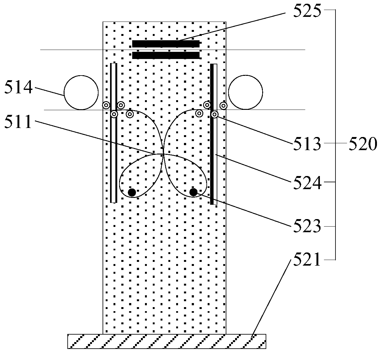
[0046] A sinking optical fiber string 500, including a butterfly-shaped optical fiber 511, and an optical fiber string fixing member 520;
[0047] The butterfly-shaped optical fiber 511 includes two upper end points and two lower rings, and the butterfly-shaped optical fiber 511 is surrounded by an optical fiber;
[0048] Both sides of the front of the optical fiber string fixing member 520 are respectively provided with vertical moving grooves 524, and horizontal positioning members 513 are respectively arranged on the vertical moving grooves 524, and the horizontal positioning members 513 move vertically along the vertical moving grooves 524; Two positioners 523 are arranged between the two vertical movement slots 524;
[0049] The butterfly-shaped optical fiber 511 is arranged between two vertical moving slots 524, the two ends of the butterfly-shap...
Embodiment 2
[0056] refer to Figure 1 to Figure 3 , the technical scheme of a real-time subsidence monitoring system of the present embodiment is as follows:
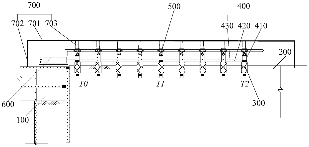
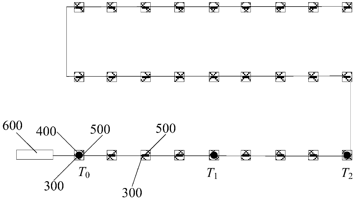
[0057] A settlement real-time monitoring system, comprising several settlement observation bases 300, at least two optical fiber static level assemblies 400, several settlement optical fiber strings 500 described in Embodiment 1, and an optical fiber demodulator 600;
[0058] The several settlement observation bases 300 are distributed in the area to be measured 200;
[0059] The fiber optic static level assembly 400 includes a fiber optic static level 410, a liquid communication pipe 420, and a level fiber 430. The fiber optic static levels 410 are respectively arranged on the settlement observation base 300, and each fiber optic static level 410 passes through The liquid communication pipes 420 are connected to each other, and each fiber optic static level 410 is connected in series with each other through the level fiber 430 an...
Embodiment 3
[0070] This embodiment provides a method for using the settlement real-time monitoring system described in Embodiment 2.
[0071] The technical scheme of a method for using a settlement real-time monitoring system of the present embodiment is as follows, including the following steps:
[0072] In the first step, the settlement real-time monitoring system is installed in the area to be tested 200;
[0073] In the second step, after the time time1 is passed, after the area 200 to be measured has settled, the settlement deformation d of the surrounding environment of each optical fiber static level 410 is measured by the optical fiber static level 410; The fiber output characteristic constant c of 511; the fiber output characteristic constant c may be wavelength, or reflectivity, or voltage, or light intensity, or fiber loss.
[0074] The third step is to fit the settlement deformation d and the optical fiber output characteristic constant c measured by at least two groups of op...
PUM
 Abstract
Description
Claims
Application Information
 - Generate Ideas
- Intellectual Property
- Life Sciences
- Materials
- Tech Scout
- Unparalleled Data Quality
- Higher Quality Content
- 60% Fewer Hallucinations
Browse by: Latest US Patents, China's latest patents, Technical Efficacy Thesaurus, Application Domain, Technology Topic, Popular Technical Reports.
© 2025 PatSnap. All rights reserved.Legal|Privacy policy|Modern Slavery Act Transparency Statement|Sitemap|About US| Contact US: help@patsnap.com