Residual current detection and correction device, detection method and electrical fire monitoring system

A technology of residual current and correction devices, which is applied in the direction of measuring devices, measuring current/voltage, electric fire alarms, etc., can solve problems such as false alarms, missed alarms, and signal inability to transmit, so as to improve safety and accuracy degree of effect

Pending Publication Date: 2020-05-08
天津市中力神盾电子科技有限公司
View PDF0 Cites 3 Cited by
  • Summary
  • Abstract
  • Description
  • Claims
  • Application Information

AI Technical Summary

Problems solved by technology

[0003] The change of the residual current will be affected by the external environment. For example, at different ambient temperatures, the value of the residual current detected by the residual current detection system is different; when the external environment affects the residual current value detected by the residual current detection system. The residual current detection system will transmit the signal of detecting a large residual current value to the alarm system, and false alarms will occur; when the residual current value detected by the environmental impact detection residual current system is too small, the residual current detection system will detect The signal of the small residual current value cannot be transmitted to the alarm system, and the situation of false alarm occurs
The change of residual current will also be affected by the load current. For example, under the influence of different load currents, the residual current detected by the residual current detection system will have different degrees of error, resulting in the residual current value detected by the residual current detection system. The signal is transmitted to the alarm system, and false alarms occur

Method used


Image

  • Residual current detection and correction device, detection method and electrical fire monitoring system
  • Residual current detection and correction device, detection method and electrical fire monitoring system
  • Residual current detection and correction device, detection method and electrical fire monitoring system

Examples


Embodiment 1

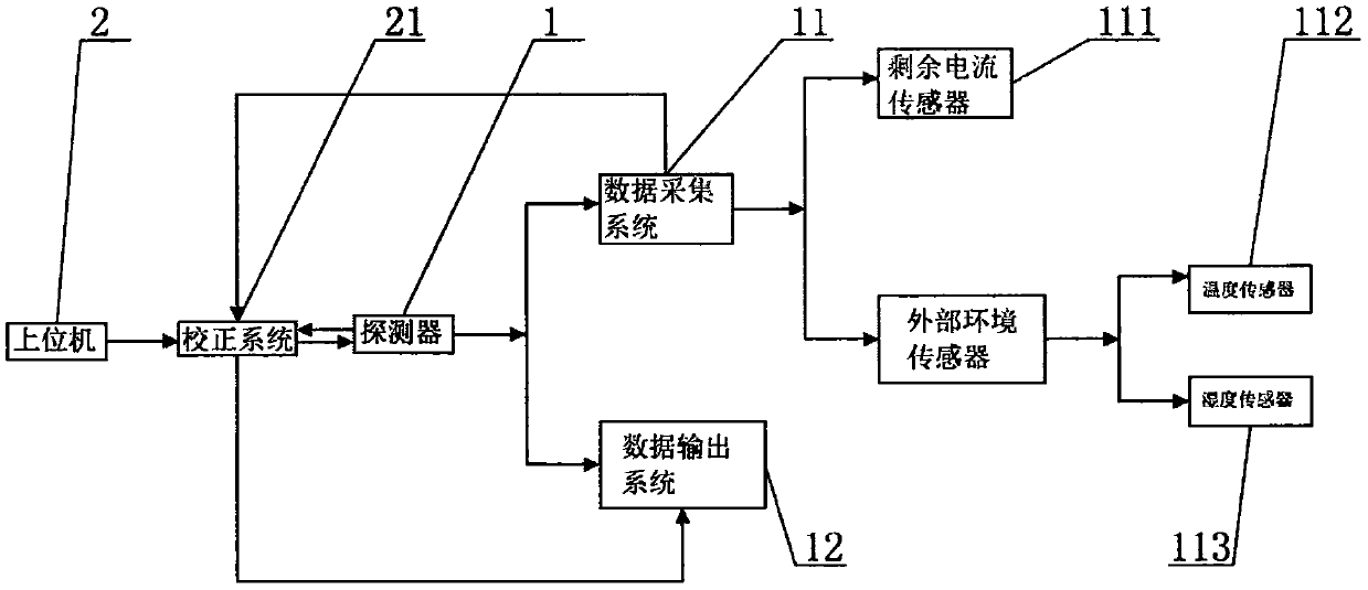
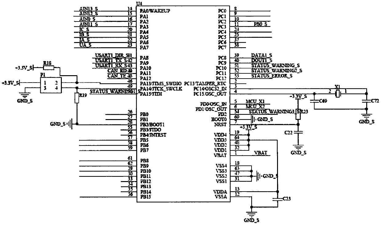
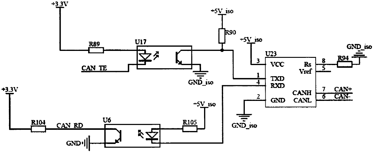
[0046] figure 1 A block diagram of a residual current detection and correction device is provided for Embodiment 1 of the present invention; figure 2 A circuit diagram of a data acquisition system is provided for Embodiment 1 of the present invention; image 3 Provide the circuit diagram of the intercommunication between the data acquisition system and the host computer for Embodiment 1 of the present invention; Figure 4 A circuit diagram for temperature collection is provided for Embodiment 1 of the present invention; Figure 5 Provide a circuit diagram of residual current acquisition for Embodiment 1 of the present invention; Figure 6 Provide a flowchart of a residual current detection and correction method for Embodiment 1 of the present invention; Figure 7 A fitting curve diagram of environmental parameters and corresponding residual current parameter changes is provided for Embodiment 1 of the present invention.

[0047] Such as figure 1 As shown, the residual cu...

Embodiment 2

[0100] Figure 8 A block diagram of a residual current detection and correction device is provided for Embodiment 2 of the present invention; Figure 9 A circuit diagram collected by the wet temperature sensor 114 is provided for Embodiment 2 of the present invention.

[0101] Such as Figure 8-9 As shown, the difference between the residual current detection and correction device provided by the second embodiment of the present invention and the first embodiment is that the environmental sensor also includes a wet temperature sensor 114 .

[0102] Specifically, different temperature signals and humidity signals are sensed by the wet temperature sensor 114, and a plurality of temperature signals and humidity signals are transmitted to the correction system 21 of the upper computer 2; The residual current, and then the correction system 21 calculates the change curve through multiple temperature signals, humidity signals and multiple corresponding residual current signals, an...

Embodiment 3

[0105] Figure 10 A block diagram of a residual current detection and correction device is provided for Embodiment 3 of the present invention; Figure 11 A circuit diagram of load current collection is provided for Embodiment 3 of the present invention; Figure 12 A flow chart of a residual current detection and correction method is provided for Embodiment 3 of the present invention.

[0106] Such as Figure 10 As shown, the difference between the residual current detection and correction device provided by the third embodiment of the present invention and the first embodiment is that the detector 1 includes a residual current sensor 111 and a load current sensor 115 .

[0107] Specifically, the load current sensor 115 senses the current value of the load current, and the residual current sensor 111 senses the residual current value under the corresponding load, records multiple corresponding residual current values ​​under multiple load currents, and forms a calibration cur...


PUM


Abstract

The invention provides a residual current detection and correction device, a detection method and an electrical fire monitoring system. The residual current detection and correction device comprises adetector and an upper computer. The data acquisition system is connected to the upper computer, the data acquisition system can be used for detecting and recording correction parameters under the influence of external factors, and the correction system is used for determining correction values according to the correction parameters recorded by the detector under the influence of the external factors; the correction system is connected to a data processing system, the data acquisition system is connected to the data processing system, and the data processing system is used for calculating a residual current actual output value according to a real-time residual current value detected by the data acquisition system and a correction value of the correction system. According to the residual current detection and correction device provided by the invention, the correction parameters acquired by the detector are sent to the upper computer, the correction system calculates a correction valueand feeds back the correction value to the detector, and the detector calculates the residual current actual output value, so that the situations of false alarm and missing alarm are avoided, and thesafety of an electrical fire monitoring system is improved.

Description

technical field [0001] The invention belongs to the technical field of high and low voltage power distribution equipment, and in particular relates to a residual current detection and correction device, a detection and correction method, and an electrical fire monitoring system. Background technique [0002] Residual current refers to the current in which the vector sum of the currents of each phase (including the neutral line) in the low-voltage distribution line is not zero. In layman's terms, when something happens on the power consumption side, the current flows from the electrified body through the human body to the earth, so that the magnitude of the current in the incoming and outgoing lines of the main circuit is different. At this time, the instantaneous vector synthetic effective value of the current is called residual current, commonly known as leakage. As the residual current changes, it indicates that the insulation of the charged conductor to the ground is dama...

Claims


Application Information

Patent Timeline
Patent Type & Authority Applications(China)
IPC IPC(8): G01R19/165G01R35/02G08B17/06
CPCG01R19/16571G01R35/02G08B17/06
Inventor 孙巍巍
Owner 天津市中力神盾电子科技有限公司
Why Eureka
Try Eureka