Bus differential protection interval CT secondary winding polarity consistency verification method

A busbar differential protection and busbar protection technology, which is applied in the direction of electric winding testing, measuring devices, instruments, etc., can solve the problems of inability to judge the polarity consistency of the CT secondary winding connected to the busbar protection, unintuitive, low efficiency, etc.

Active Publication Date: 2020-05-08
SHENZHEN POWER SUPPLY BUREAU
View PDF7 Cites 2 Cited by
  • Summary
  • Abstract
  • Description
  • Claims
  • Application Information

AI Technical Summary

Problems solved by technology

However, the above-mentioned consistency verification method is inefficient and unintuitive, and it cannot simulate the real situation of the equipment under load.
[0004] Therefore, there is an urgent need for a method for verifying the consistency of the polarity of the CT secondary windings in each interval of the busbar differential protection, which can truly simulate the secondary current of the primary equipment under load during the acceptance stage to ensure that each of the connected busbar protection The consistency of the polarity of the secondary winding of the interval CT can effectively avoid the inability to judge the consistency of the polarity of the secondary winding of the CT connected to the busbar protection due to the inability of the newly put into operation equipment to carry the load effectively, which may lead to large-scale power outages in the power grid phenomenon occurs

Method used


Image

  • Bus differential protection interval CT secondary winding polarity consistency verification method
  • Bus differential protection interval CT secondary winding polarity consistency verification method
  • Bus differential protection interval CT secondary winding polarity consistency verification method

Examples


Embodiment Construction

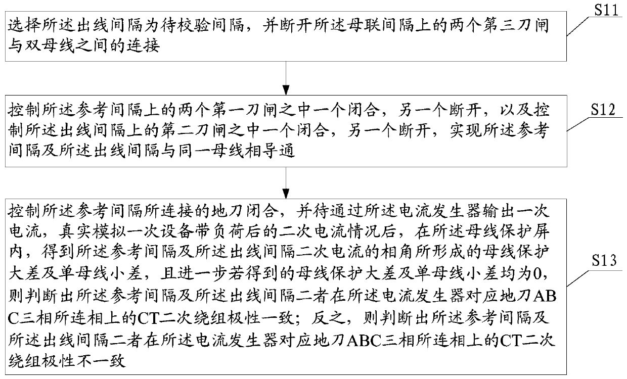
[0053] In order to make the object, technical solution and advantages of the present invention clearer, the present invention will be further described in detail below in conjunction with the accompanying drawings.

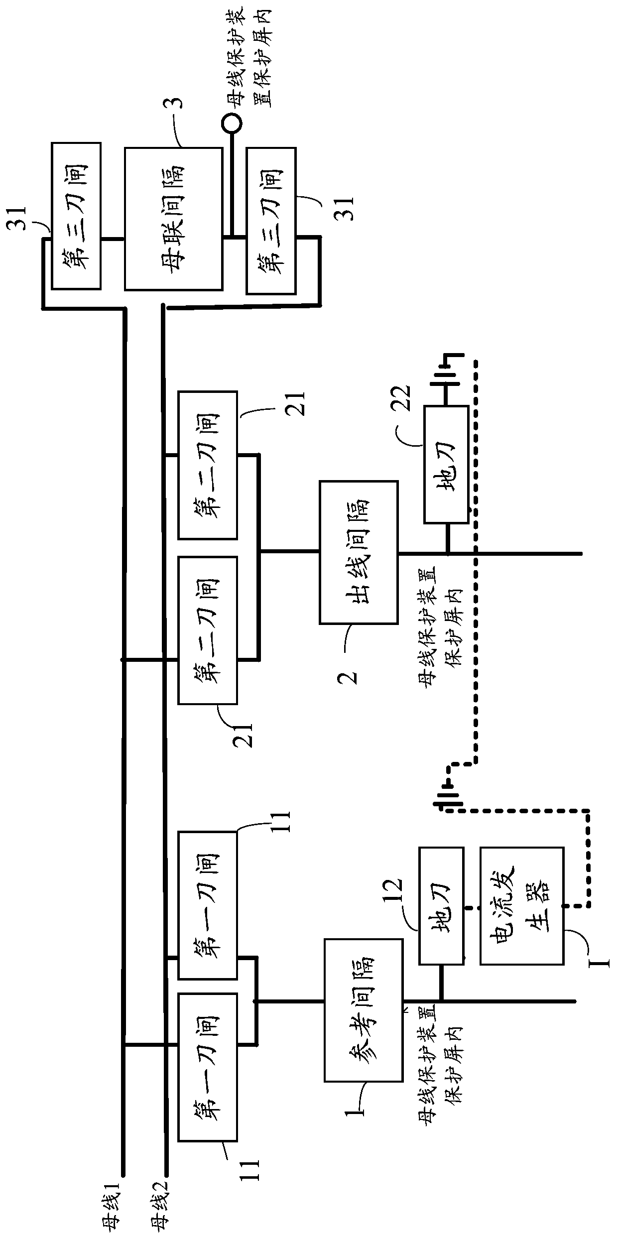
[0054] Such as figure 1 As shown, in Embodiment 1 of the present invention, a method for verifying the consistency of the polarity of the CT secondary windings in each interval of the bus differential protection is provided, which is implemented in the bus protection of the dual bus connection substation configuration; wherein,

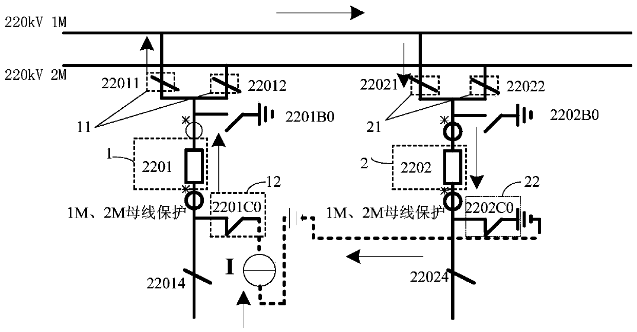
[0055] Such as figure 2 As shown, the busbar protection of the double-bus connection substation is formed with a reference interval 1, an outgoing line interval 2, and a bus coupler interval 3;

[0056] One end of the reference interval 1 is respectively connected to double busbars (such as 1M and 2M) through two first knife gates 11, and the other end is connected to one of the ABC three-phases of a ground knife 12 in the bus protectio...


PUM


Abstract

The invention provides a bus differential protection interval CT secondary winding polarity consistency verification method, which is realized in bus protection configured in a double-bus wiring transformer substation, and a reference interval, an outgoing line interval and a bus coupler interval are formed on the bus protection. The method comprises the following steps: selecting an outgoing lineinterval as a to-be-verified interval, and disconnecting a bus coupler interval from double buses; controlling disconnectors on the reference interval and the outgoing line interval to be switched onor switched off to be conducted with the same bus; controlling a grounding disconnector connected with the reference interval to be closed, outputting primary current through a current generator to truly simulate the secondary current condition after primary equipment is loaded, and if it is detected that the bus protection large difference and the single bus small difference are both 0, determining that the polarities of CT secondary windings on the same phase of the reference interval and the outgoing line interval are consistent; otherwise, determining inconsistency. Through the method, asecondary current condition after the primary equipment is loaded is truly simulated through a primary up-flow method, and the polarity consistency of CT secondary windings at each interval of accessed bus protection is ensured.

Description

technical field [0001] The invention relates to the technical field of substation relay protection testing, in particular to a method for verifying the consistency of the polarity of secondary windings of CTs in each interval of busbar differential protection. Background technique [0002] The busbar is the key equipment of the substation. As the main protection of the busbar, the differential protection of the busbar will cause immeasurable impact on the substation and even the entire power grid, and seriously affect the stable operation of the power grid. From the composition principle of busbar differential protection, it can be seen that the key factor affecting the correct operation of busbar protection lies in the correctness of the wiring of the CT secondary circuit of each interval connected to the busbar differential protection, and the key factor determining the correctness of the wiring of the CT secondary circuit is The polarity of the CT secondary windings of ea...

Claims


Application Information

Patent Timeline
Patent Type & Authority Applications(China)
IPC IPC(8): G01R31/72G01R35/00
CPCG01R35/00
Inventor 乔中伟钱敏王世祥谷斌苏靖
Owner SHENZHEN POWER SUPPLY BUREAU
Why Eureka
Try Eureka