
Unmanned aerial vehicle cluster path planning processing method based on artificial potential field and unmanned aerial vehicle

An artificial potential field method and path planning technology, applied in the field of unmanned aerial vehicles, can solve the problems of large amount of calculation, complicated mutual avoidance rules of unmanned aerial vehicles, lack of integrity, etc., to achieve easy implementation and good effect of swarm control of unmanned aerial vehicles Effect

Pending Publication Date: 2020-05-08
一飞智控(天津)科技有限公司
View PDF10 Cites 7 Cited by
  • Summary
  • Abstract
  • Description
  • Claims
  • Application Information

AI Technical Summary

Problems solved by technology

[0003] To sum up, the problems in the existing technology are: the path planning of large-scale UAV formation is relatively complicated, and there is a lack of effective algorithms to quickly realize the path planning of UAV formation formation transformation.
[0005] When there are many individuals in the UAV formation and the distance is close, the mutual avoidance rules between UAVs are more complicated, lack integrity, and require a large amount of calculation

Method used


Image

  • Unmanned aerial vehicle cluster path planning processing method based on artificial potential field and unmanned aerial vehicle
  • Unmanned aerial vehicle cluster path planning processing method based on artificial potential field and unmanned aerial vehicle
  • Unmanned aerial vehicle cluster path planning processing method based on artificial potential field and unmanned aerial vehicle

Examples


Embodiment Construction

[0047] In order to make the object, technical solution and advantages of the present invention clearer, the present invention will be further described in detail below in conjunction with the examples. It should be understood that the specific embodiments described here are only used to explain the present invention, not to limit the present invention.

[0048] Aiming at the problems existing in the prior art, the present invention provides a UAV cluster path planning processing method based on an artificial potential field and a UAV. The present invention will be described in detail below with reference to the accompanying drawings.

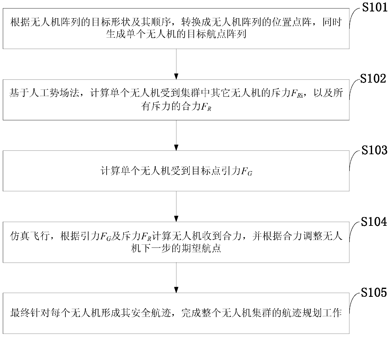
[0049] like figure 1 As shown, the artificial potential field-based UAV cluster path planning processing method provided by the embodiment of the present invention includes the following steps:

[0050] S101: According to the target shape and sequence of the UAV array, convert it into a position lattice of the UAV array, and simultaneously gene...


PUM


Abstract

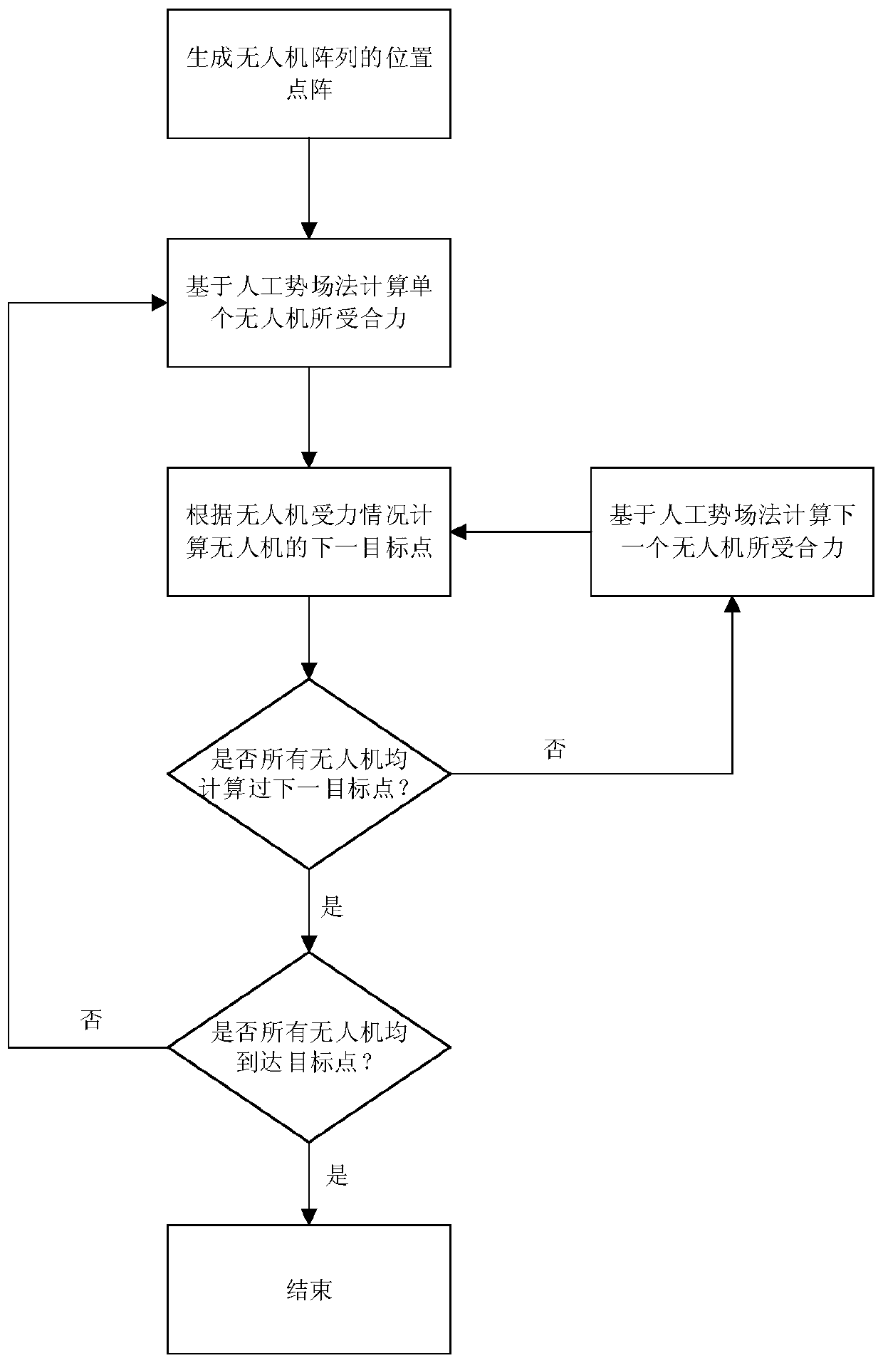
The invention, which belongs to the technical field of unmanned aerial vehicle cluster control, discloses an unmanned aerial vehicle cluster path planning processing method based on an artificial potential field, and an unmanned aerial vehicle. The method comprises the steps: carrying out conversion to obtain a position dot matrix of an unmanned aerial vehicle array according to a target shape andsequence of the unmanned aerial vehicle array, and generating a target waypoint array of a single unmanned aerial vehicle; on the basis of an artificial potential field method, calculating a repulsive force FRi of the single unmanned aerial vehicle by other unmanned aerial vehicles in the cluster and a resultant force FR of all the repulsive forces; calculating a target point gravitation FG of the single unmanned aerial vehicle; simulating flight, calculating a resultant force received by the unmanned aerial vehicle according to the gravitation FG and the repulsion FR, and adjusting an expected waypoint of the unmanned aerial vehicle in the next step according to the resultant force; and finally, forming a safe track for each unmanned aerial vehicle to finish the track planning work of the whole unmanned aerial vehicle cluster. The method is suitable for solving a path planning problem of a large-scale unmanned aerial vehicle cluster during formation flight, and the unmanned aerial vehicle cluster path planning processing method has the characteristics of easiness in implementation, high safety, high reliability and good unmanned aerial vehicle cluster control effect.

Description

technical field [0001] The invention belongs to the technical field of UAV cluster control, and in particular relates to a UAV cluster path planning processing method based on an artificial potential field and a UAV. Background technique [0002] At present, the closest existing technology: As UAVs are increasingly used in military and civil fields, the related path planning issues have also attracted extensive attention from scientific researchers in various countries. Under the vigorous promotion of computer technology and aerospace technology, UAV path planning system plays a vital role in the process of UAV performing combat missions. The purpose of UAV path planning is to plan a flight path that meets the constraints according to mission requirements, which is the core part of UAV mission planning. [0003] To sum up, the problems in the existing technology are: the path planning of large-scale UAV formation is relatively complicated, and there is a lack of effective a...

Claims


Application Information

Patent Timeline
IPC IPC(8): G05D1/10
CPCG05D1/104
Inventor 吴冲孙航
Owner 一飞智控(天津)科技有限公司
Learn More