Eureka AIR delivers breakthrough ideas for toughest innovation challenges, trusted by R&D personnel around the world.

Method for obtaining windward side pressure center position and area of spacecraft

A space vehicle, windward side technology, applied in geometric CAD and other directions, can solve problems such as unsatisfactory accuracy, difficult to achieve, complex shape, etc., to achieve the effect of simple preparation, adjustable calculation accuracy, and strong operability

Pending Publication Date: 2020-05-08
SHANGHAI SATELLITE ENG INST
View PDF4 Cites 4 Cited by
  • Summary
  • Abstract
  • Description
  • Claims
  • Application Information

AI Technical Summary

Problems solved by technology

However, for a small number of space vehicles with complex shapes, due to their irregular shapes, the pressure center and area of ​​the windward side can no longer be calculated according to the regular geometric dimensions. The traditional method is to calculate the pressure center by simplifying the geometric shape and area, but simplification will bring large errors, and this simplification calculation usually assumes that the spacecraft is flying at zero attitude, and it is difficult to realize the situation of flying at any attitude
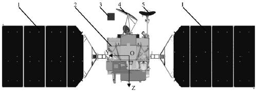
For example, a space vehicle operating in low orbit has a complex shape because it is equipped with a one-dimensional conical scanning microwave detector with a large reflector, a two-dimensionally driven data transmission relay antenna with a large-aperture reflector, and a one-dimensionally driven biplane biased solar cell. array and other protruding parts, and the driving angle of these driving parts changes with time, which also makes the windward side of the spacecraft change constantly. The change of the windward side leads to the constant change of the position of the center of pressure. In order to calculate its different rotation conditions in different attitudes The position and area of ​​the center of pressure on the windward side, the accuracy of the simplified method cannot be satisfied, and the efficiency is not high

Method used


Image

  • Method for obtaining windward side pressure center position and area of spacecraft
  • Method for obtaining windward side pressure center position and area of spacecraft
  • Method for obtaining windward side pressure center position and area of spacecraft

Examples


Embodiment Construction

[0043] The present invention will be described in detail below in conjunction with specific embodiments. The following examples will help those skilled in the art to further understand the present invention, but do not limit the present invention in any form. It should be noted that those skilled in the art can make several changes and improvements without departing from the concept of the present invention. These all belong to the protection scope of the present invention.

[0044] Such as figure 1 As shown, a method for obtaining the center-of-pressure position and area of ​​the windward side of a spacecraft provided in this embodiment includes the following steps:

[0045] Step 1, establish a three-dimensional geometric model of a standard reference body at a position near the spacecraft, such as figure 2 As shown, the components of a space vehicle in the figure include a one-dimensional drive offset solar cell array, a space vehicle body, a one-dimensional drive remote...


PUM


Abstract

The invention provides a method for obtaining the pressure center position and area of the windward side of a spacecraft. The method comprises the steps: establishing a three-dimensional geometric model of a standard reference body at the position near the spacecraft; creating a parallel projection plane graph of the standard reference body and the spacecraft along the flight direction; identifying and extracting a standard reference body area and a spacecraft area in the projection plane graph; calculating the image size, the centroid coordinate value and the total pixel number of the extracted standard reference body area; calculating a centroid coordinate value and a total pixel number of the extracted spacecraft area; calculating a unit conversion coefficient of a standard reference body region image size and a theoretical engineering size; and calculating the windward side pressure center position and area of the spacecraft. According to the method, the pressure center position and area of the windward side of the spacecraft with the complex shape can be rapidly and accurately obtained; the applicable working conditions are multiple; the calculation precision is adjustable, and the operability is high.

Description

technical field [0001] The invention relates to the technical field of overall design of a spacecraft, in particular to a method for obtaining the position and area of ​​the pressure center of a windward surface of a spacecraft. Background technique [0002] Space vehicles, especially low-orbit space vehicles flying around the earth, when the aerodynamic point (center of pressure) on the windward side does not pass through the center of mass of the space vehicle during flight, this pressure eccentricity will disturb the flight attitude of the space vehicle . When the altitude of the flight orbit is lower, the density of the atmosphere is greater, and the area facing the wind is larger, the attitude disturbance torque caused by the eccentricity of the atmospheric pressure will be greater. The attitude instability of the spacecraft is caused, and the spacecraft enters the emergency attitude safety mode, thereby interrupting the normal business operation. Therefore, it is par...

Claims


Application Information

Patent Timeline
IPC IPC(8): G06F30/15
CPCY02T90/00
Inventor 丁丕满邵益凯冯彦军王震汪自军袁金如潘高伟张宏伟周徐斌钱斌陈建新
Owner SHANGHAI SATELLITE ENG INST
Why Eureka
Eureka Blog
Learn More