Wire clamp mounting tool and intelligent equipment

A technology for installing tools and wire clips, which is applied to overhead lines/cable equipment, etc., can solve the problems of labor-intensive operation and danger of connecting and draining lines, and achieves the effects of compact structure, prevention of electric shock, and convenient use.

Pending Publication Date: 2020-05-08
BEIJING GUODIAN FUTONG SCI & TECH DEV +1
View PDF0 Cites 6 Cited by
  • Summary
  • Abstract
  • Description
  • Claims
  • Application Information

AI Technical Summary

Problems solved by technology

[0003] Therefore, the technical problem to be solved by the present invention is to overcome the defects of high labor intensity and dangerous operation in the connection and drainage operation in the prior art, so as to provide a wire clamp installation tool with high degree of automation, low labor intensity and safer , Smart Gear with this Clamp Installation Tool

Method used


Image

  • Wire clamp mounting tool and intelligent equipment
  • Wire clamp mounting tool and intelligent equipment
  • Wire clamp mounting tool and intelligent equipment

Examples


Embodiment 1

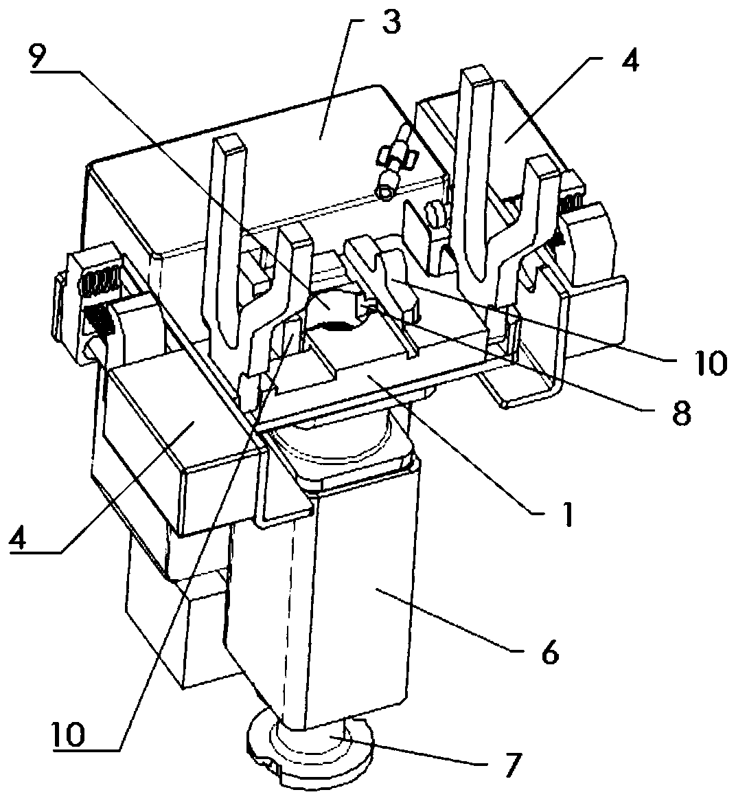
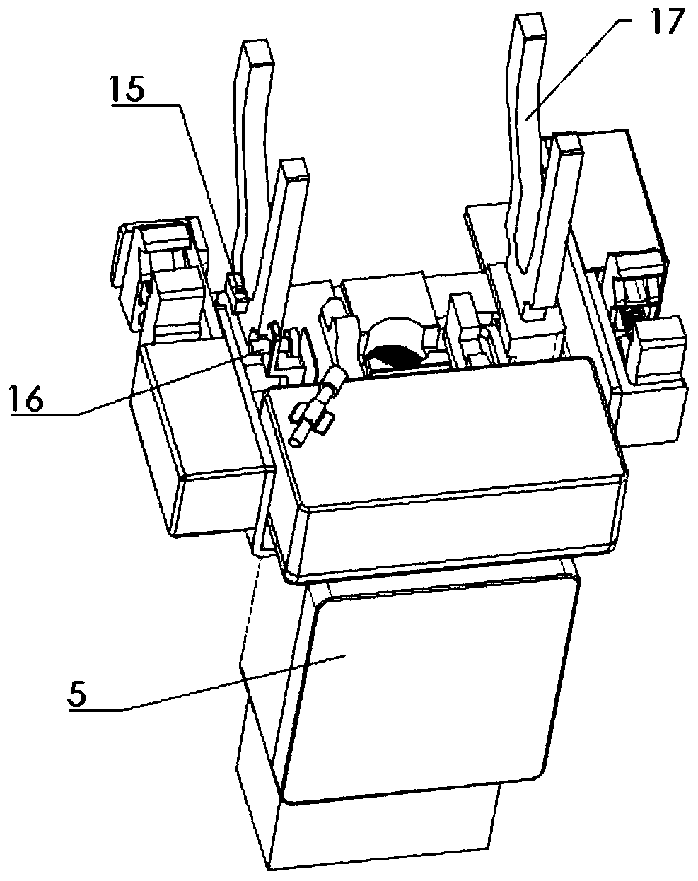
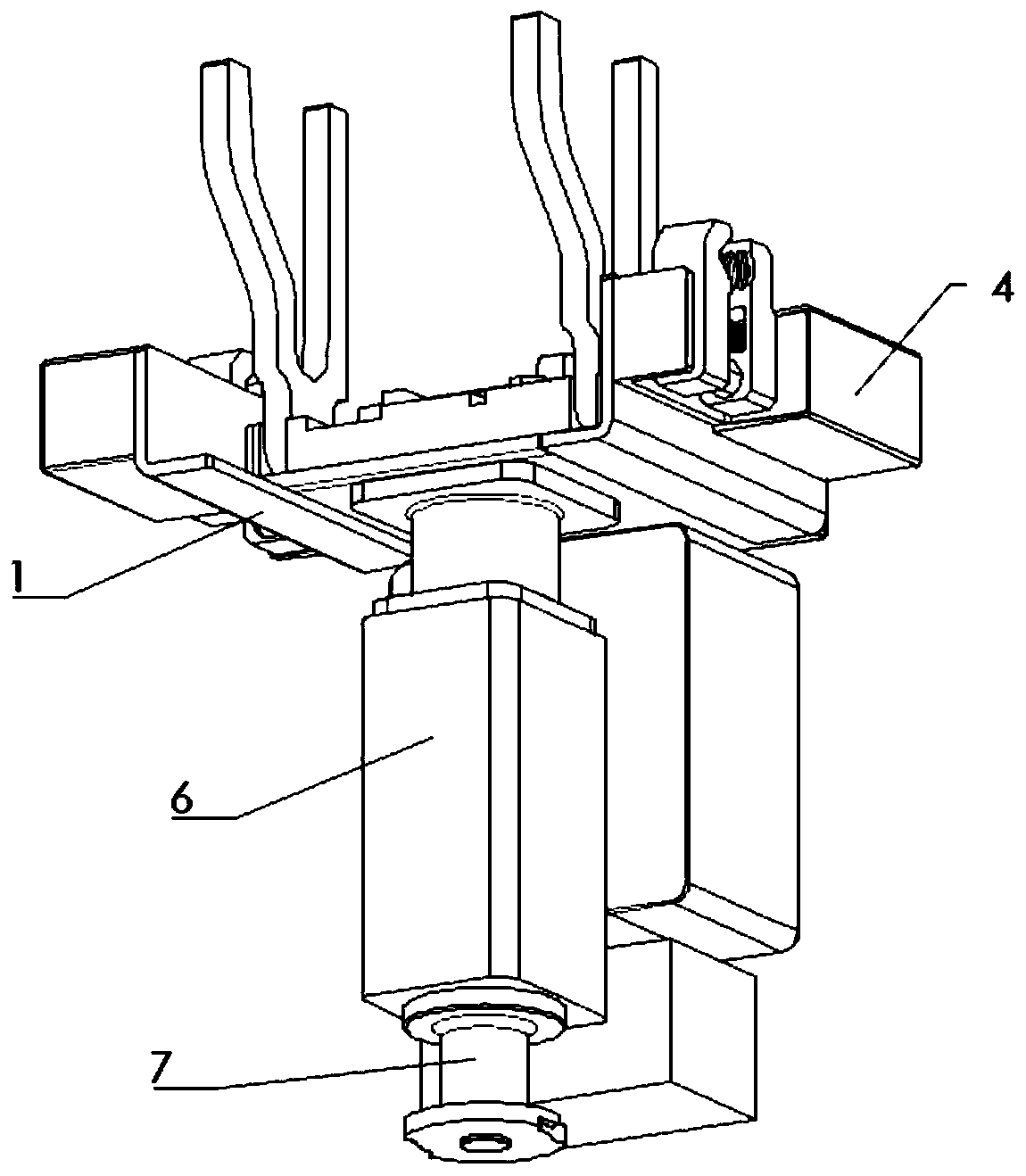
[0036] The clamp installation tool in this embodiment, such as figure 1 - Figure 7 As shown, it includes a frame body 1, a clamping mechanism 3, the wire locking mechanism 4, a controller 5, a wire driving mechanism and an induction component.

[0037]The frame body 1 is installed on the moving arm, and the clamping mechanism 3 , the wiring mechanism 2 and the controller 5 are installed on the frame body 1 to provide support for the clamping mechanism 3 , the wiring mechanism 2 and the controller 5 . The rack body 1 has a placement portion for placing the wiring mechanism 2 . In this embodiment, the placement part is located at the middle of the frame body 1, and the wiring driving mechanism is located at the lower side of the placement part. Therefore, in order to ensure that the placement position of the wiring mechanism 2 is relatively accurate, the tightening part 23 is connected to the wiring driving mechanism, and the placement part has a groove 8 for positioning the ...

Embodiment 2

[0053] The smart equipment in this embodiment has the wire clamp installation tool in Embodiment 1, and a moving arm for installing the wire clamp installation tool. When the intelligent device drives the live connection of the drain wire, first install the wiring mechanism 2 on the placement part of the frame body 1. The way to install the wiring mechanism 2 can be manually placed, or it can be taken by a manipulator or the like, and then placed by a manipulator. The way of taking and placing is more automated. Then, the drain wire 25 and the main wire 24 are installed in the wiring mechanism 2 and the wire locking mechanism 4 successively by moving the movable arm. After the drain wire 25 and the main wire 24 are electrically connected, the wire locking mechanism 4 unclamps the main wire 24 and After the drain wire 25 and the clamping mechanism 3 loosen the wiring mechanism 2, the clamp installation tool moves away from the position of the wiring mechanism 2 to complete a li...


PUM


Abstract

The invention relates to the technical field of wiring devices, and particularly relates to a wire clamp mounting tool and intelligent equipment. The wire clamp mounting tool comprises a frame body, aclamping mechanism, a wiring mechanism and a controller. The frame body is mounted on a moving arm and is provided with a placing part for placing the wiring mechanism; the clamping mechanism is installed on the frame body and is provided with a clamping end which is located at the placing part and clamps the wiring mechanism; a wire locking mechanism is arranged on the frame body corresponding to the wiring mechanism; when the moving arm moves, a main wire and a drainage wire are correspondingly connected into the wire locking mechanism and the wiring mechanism respectively, and the main wire and the drainage wire are fixed by the wire locking mechanism; and the controller is connected with the clamping mechanism, the wire locking mechanism and a wiring driving mechanism for driving thewiring mechanism to carry out wiring, and controls actions of the clamping mechanism, the wire locking mechanism and the wiring driving mechanism. The wire clamp mounting tool is high in automation degree, low in labor intensity and safer.

Description

technical field [0001] The invention relates to the technical field of wiring devices, in particular to a wire clamp installation tool and intelligent equipment. Background technique [0002] Distribution network lines need frequent testing, inspection and maintenance during long-term operation. Distribution network live work has become the most direct and effective means to reduce distribution network outage time, improve power supply reliability and service level, such as live connection operation. Drain line connection generally refers to the use of J-shaped clamps to take power from the main cable to the branch cable, and the branch cable is connected to the terminal to supply power to the terminal. The traditional work of connecting and draining live wires mainly relies on manual work, using the glove method, that is, the operators use the insulated bucket truck to insulate and isolate the ground, wear insulated clothing and insulated gloves, and inspect the exposed wi...

Claims


Application Information

Patent Timeline
Patent Type & Authority Applications(China)
IPC IPC(8): H02G1/04
CPCH02G1/04
Inventor 张五福李文华滕济林赵崇王朝阳卢路徐善军
Owner BEIJING GUODIAN FUTONG SCI & TECH DEV
Why Eureka
Try Eureka