
Industrial automatic liquid stirring and conveying device

An industrial automation and conveying device technology, which is applied in mixers with rotating mixing devices, transportation and packaging, mixer accessories, etc., can solve the problems of reduced motor drive efficiency and idling of mixing devices, and achieves improved ease of use and improved work. Efficiency, avoid the effect of irregular swing

Inactive Publication Date: 2020-05-12
XIAN HUIFU RONGTONG INFORMATION TECH CO LTD
View PDF1 Cites 0 Cited by
  • Summary
  • Abstract
  • Description
  • Claims
  • Application Information

AI Technical Summary

Problems solved by technology

[0004] The purpose of the present invention is to provide an industrial automation liquid stirring and conveying device to solve the problem that when the amount of liquid is not completely filled inside the device, the part of the stirring device for stirring will be idling, which will cause the failure of the motor. The problem of reduced driving efficiency

Method used


Image

  • Industrial automatic liquid stirring and conveying device
  • Industrial automatic liquid stirring and conveying device
  • Industrial automatic liquid stirring and conveying device

Examples


Embodiment 1

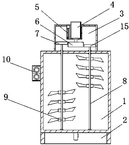
[0021] Embodiment 1: An industrial automatic liquid stirring and conveying device, comprising a stirring box body 1, a motor 4 and a screw stepping motor 5, the bottom end of the stirring box body 1 is fixedly installed with a base 2, and the stirring box body 1 An operation button 10 is fixedly installed at the middle position of the outer side wall.

Embodiment 2

[0022] Embodiment 2: Stirring device is fixedly installed in the inside of stirring box casing 1, and stirring device comprises fixed box 3, motor 4, screw mandrel stepping motor 5, first gear 6, second gear 7, first transmission rod 8, The second transmission rod 9 and the third gear 15, the top of the mixing box casing 1 is fixedly equipped with a fixed box 3, and the inner top of the fixed box 3 is fixed with a screw stepping motor 5 by bolts, and the screw stepping motor 5 The model is FSL40, and the slider of the screw stepping motor 5 is fixed with a motor 4 by bolts, the model of the motor 4 is YS90-2, the input end of the motor 4 is electrically connected with the output end of the operation button 10, and the operation button The input end of 10 is electrically connected to the external power supply, the output end of the motor 4 is fixedly installed with the first gear 6, and the inner two sides of the mixing box body 1 are respectively fixedly installed with the firs...

Embodiment 3

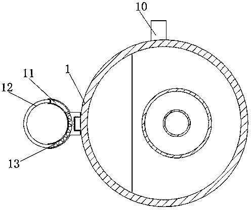
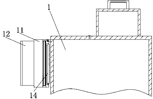
[0023] Embodiment 3: The outside of the mixing box body 1 is provided with a delivery pipe fixing device, the delivery pipeline fixing device includes a support seat 11, a limit rod 12, a spring 13 and a support rod 14, and the front end of the mixing box box body 1 is connected to the support by a rotating shaft. The seat 11 is fixedly connected, and the inside of the support seat 11 is provided with a setting groove, and the inside of the setting groove is fixedly installed with a support rod 14 through a rotating shaft. The side of the setting groove is designed to be inclined, and the fixed end of the support rod 14 is designed to be inclined. , the inclination angles of the two sets of inclined designs are the same, through this design, the setting groove can form a limit effect on the support rod 14, and when the support rod 14 contacts the side wall of the mixing box body 1, the mixing box body 1 can pass through The support rod 14 and the support seat 11 form a relative...


PUM


Abstract

The invention discloses an industrial automatic liquid stirring and conveying device, which comprises a stirring box body, a motor and a lead screw stepping motor, wherein a base is fixedly installedat the bottom end of the stirring box body, an operation button is fixedly installed in the middle of the outer side wall of the stirring box body, a stirring device is fixedly installed in the stirring box body, and a conveying pipe fixing device is arranged outside the stirring box body. According to the invention, the device is provided with a fixed box, the motor, the lead screw stepping motor, a first gear, a second gear, a first transmission rod, a second transmission rod and a second gear, so that the problem that when the interior of the device is not completely filled with a liquid, part of stirring devices for stirring idles so as to reduce the driving efficiency of the motor is solved, and the working efficiency of the device is improved; and the industrial automatic liquid stirring and conveying device is provided with a supporting seat, a limiting rod, a spring and a supporting rod, so that the usability of the device is improved.

Description

technical field [0001] The invention relates to the technical field of stirring and conveying devices, in particular to an industrial automation liquid stirring and conveying device. Background technique [0002] For example, the Chinese Patent Publication No. is: CN207980960U, a kind of industrial automatic liquid stirring and conveying device, including a housing, a temperature controller and a liquid storage tank, the outer surface of the housing is provided with a glass observer, and the glass observer is embedded in the housing Among them, the top of the shell is equipped with a temperature controller, and the temperature controller is embedded in the shell, and the inside of the temperature controller is equipped with a micro motor, and the micro motor and the temperature controller are closely attached. This kind of industrial automation Liquid stirring and conveying device, the outer surface of the stirring rod is equipped with stirring blades, and the stirring blade...

Claims


Application Information

Patent Timeline
IPC IPC(8): B01F7/18B01F15/02
CPCB01F27/191B01F27/85B01F27/90B01F35/717
Inventor 叶晋
Owner XIAN HUIFU RONGTONG INFORMATION TECH CO LTD
Learn More