Hydraulic roller coating device with accurate coating thickness

A hydraulic and roller coating technology, which is applied to the surface coating liquid device, coating, etc., can solve the problems of high technical and experience requirements for operators, difficulty in improving production efficiency, and unstable coating thickness.

Pending Publication Date: 2020-05-12
江苏君安新材料科技有限公司
View PDF0 Cites 0 Cited by
  • Summary
  • Abstract
  • Description
  • Claims
  • Application Information

AI Technical Summary

Problems solved by technology

The thickness of the paint layer is related to the pressure and gap between the coating roller and the surface of the substrate. The existing roller coating equipment adjusts the coating pressure between the coating roller and the surface of the substrate by manually borrowing experience values ​​through the screw nut auxiliary adjustment mechanism. Therefore, the existing roller coating equipment has the following defects that directly affect the coating quality; firstly, the gap between the rollers and the gap between the roller and the substrate depends on the manual adjustment and control of the operator, and the adjustment accuracy is difficult to guarantee. The technical and experience requirements for operators are particularly high, and the coating t

Method used


Image

  • Hydraulic roller coating device with accurate coating thickness
  • Hydraulic roller coating device with accurate coating thickness
  • Hydraulic roller coating device with accurate coating thickness

Examples


Embodiment Construction

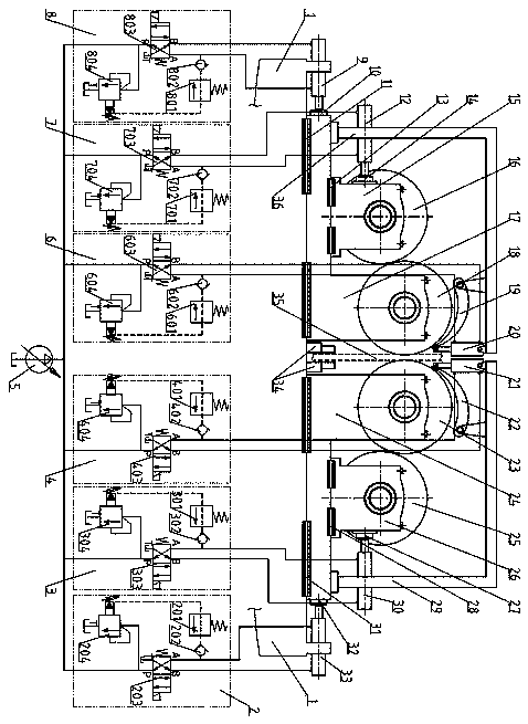
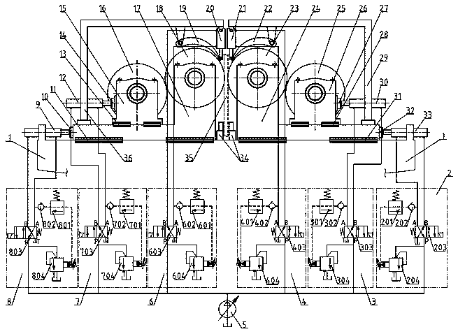
[0016] Such as figure 1 The precision coating thickness hydraulic roller coating device shown, the roller coating device includes a frame 1, and the front coating roller 23 and the back coating roller 18 are symmetrically arranged on the frame 1, and the front coating roller 23 and the back coating roller The application rollers 18 are located on both sides of the color-coated base plate 35 respectively, so as to realize the monitoring of the coating thickness on the two surfaces of the color-coated base plate 35 . The front dipping roller 25 and the back dipping roller 16 are also symmetrically arranged on the frame 1. The front dipping roller 25 and the front coating roller 23 correspond to each other to form a pair of coating dipping rollers. The back dipping roller 16 Corresponding to the back application roller 18, another pair of application stick rollers is formed. The color-coated base plate 35 is located on the symmetrical plane of the above-mentioned two coating and...


PUM


Abstract

The invention discloses a hydraulic roller coating device with the accurate coating thickness. The device comprises a machine frame, a front coating roller, a back coating roller, a front dipping roller and a back dipping roller are symmetrically arranged on the machine frame, thickness measuring sensors are arranged on the two sides of the symmetrical face, the front coating roller, the back coating roller, the front dipping roller and the back dipping roller realize sliding supporting through corresponding sliding seats, corresponding pressure sensors are arranged between the sliding seats and hydraulic cylinders, the peripheries of the front coating roller and the back coating roller are each provided with corresponding uniformizing plates at intervals, the uniformizing ends of the uniformizing plates are hinged to a support through the corresponding hydraulic cylinders, the hydraulic cylinders communicate with corresponding hydraulic positioning loops, and each hydraulic positioning loop comprises an electromagnetic reversing valve, a check valve, a remote pressure regulating valve and a pilot overflow valve. The hydraulic roller coating device not only can automatically adjustthe roller gap and coating thickness, effectively ensure accuracy of the coating thickness, but also can achieve remote adjustment control, and is high in automation degree and coating thickness accuracy.

Description

technical field [0001] The invention relates to a coating equipment used for the production of color-coated plates, in particular to a roller coating device capable of double-sided coating and precisely adjusting the thickness of the coating layer. Background technique [0002] The pre-painted steel plate is made of cold-rolled steel strip and galvanized steel strip as the substrate, and after surface pretreatment, one or more layers of liquid paint are applied to the steel strip by roller coating, and then baked and cooled to obtain the coating. Coated steel plate, coated steel plate has light weight, beautiful appearance and good corrosion resistance. It provides a new type of material for construction industry, furniture industry, electrical industry, vehicle manufacturing industry and many other industries, and plays a role in replacing wood with steel and efficient construction. , energy saving, pollution prevention and other good effects. [0003] Roller coating equip...

Claims


Application Information

Patent Timeline
IPC IPC(8): B05C1/08B05C9/04B05C11/10
CPCB05C1/08B05C1/0834B05C1/0895B05C9/04B05C11/1005
Inventor 陈钢顾国鼎
Owner 江苏君安新材料科技有限公司
Why Eureka
Try Eureka