Drainage device

A technology for drainage devices and water passages, which is applied to water supply devices, pump devices, drainage structures, etc., can solve the problems of low drainage efficiency of building drainage systems, and achieve the effects of enhancing power, good pressure relief, and improving efficiency

Pending Publication Date: 2020-05-12
HUAQIAO UNIVERSITY
View PDF1 Cites 2 Cited by
  • Summary
  • Abstract
  • Description
  • Claims
  • Application Information

AI Technical Summary

Problems solved by technology

[0003] The invention provides a drainage device aimed at improving the low drainage efficiency of building drainage systems in the prior art

Method used


Image

  • Drainage device
  • Drainage device
  • Drainage device

Examples


Embodiment Construction

[0024] In order to make the purpose, technical solutions and advantages of the embodiments of the present invention clearer, the technical solutions in the embodiments of the present invention will be clearly and completely described below in conjunction with the accompanying drawings in the embodiments of the present invention. Obviously, the described embodiments It is some embodiments of the present invention, but not all of them. Based on the implementation manners in the present invention, all other implementation manners obtained by persons of ordinary skill in the art without creative efforts fall within the protection scope of the present invention. Accordingly, the following detailed description of the embodiments of the invention provided in the accompanying drawings is not intended to limit the scope of the claimed invention, but merely represents selected embodiments of the invention. Based on the implementation manners in the present invention, all other implement...


PUM


Abstract

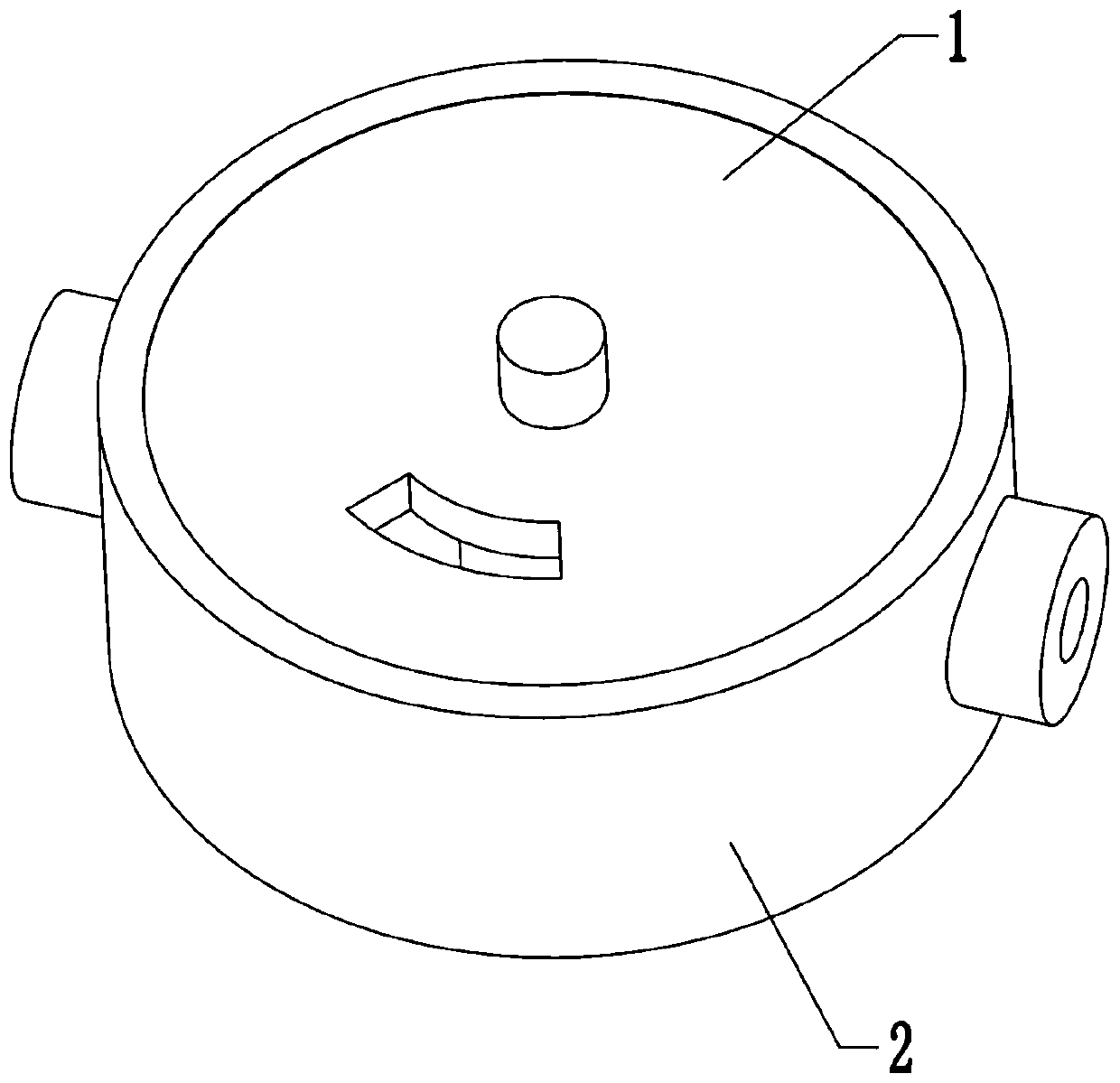
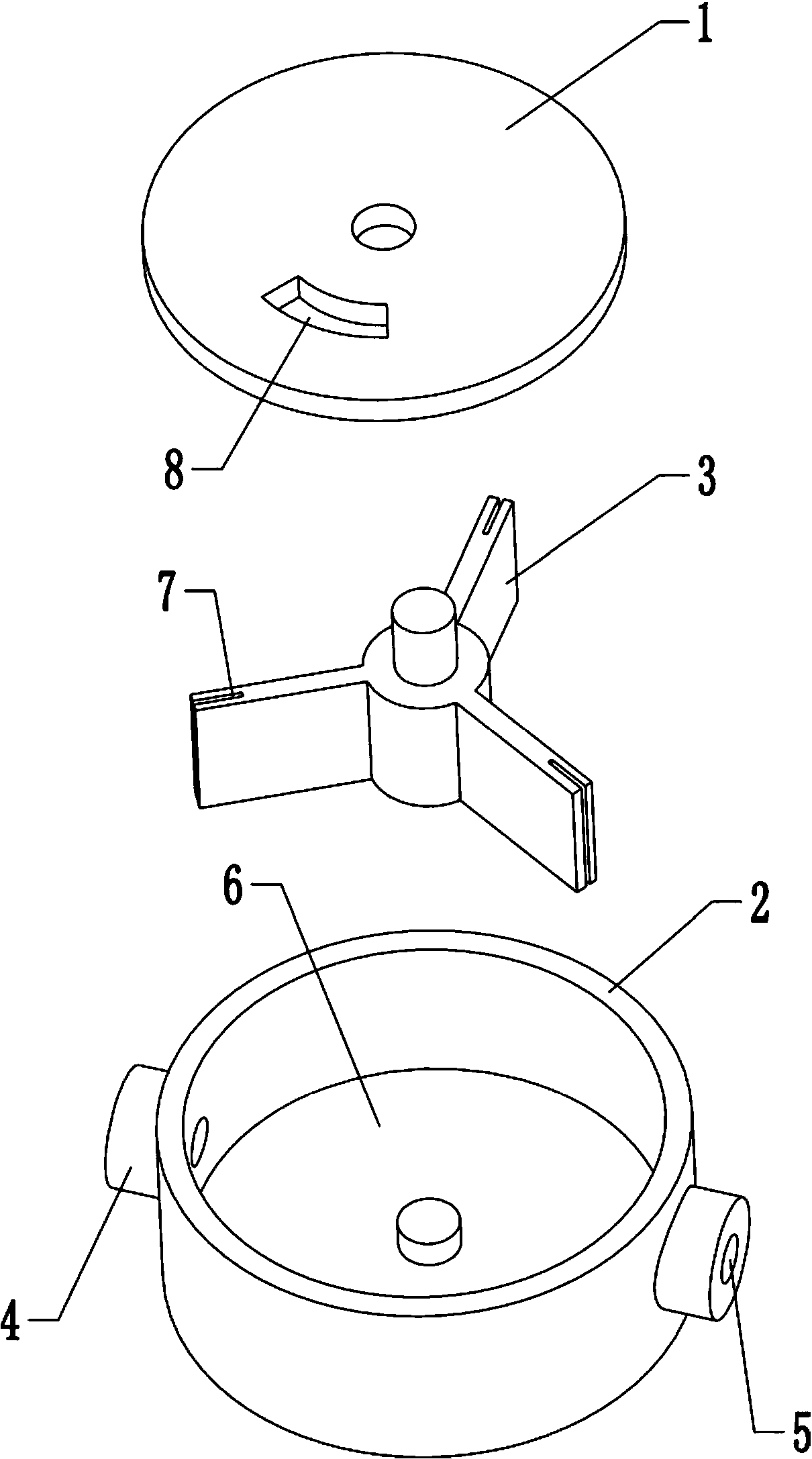
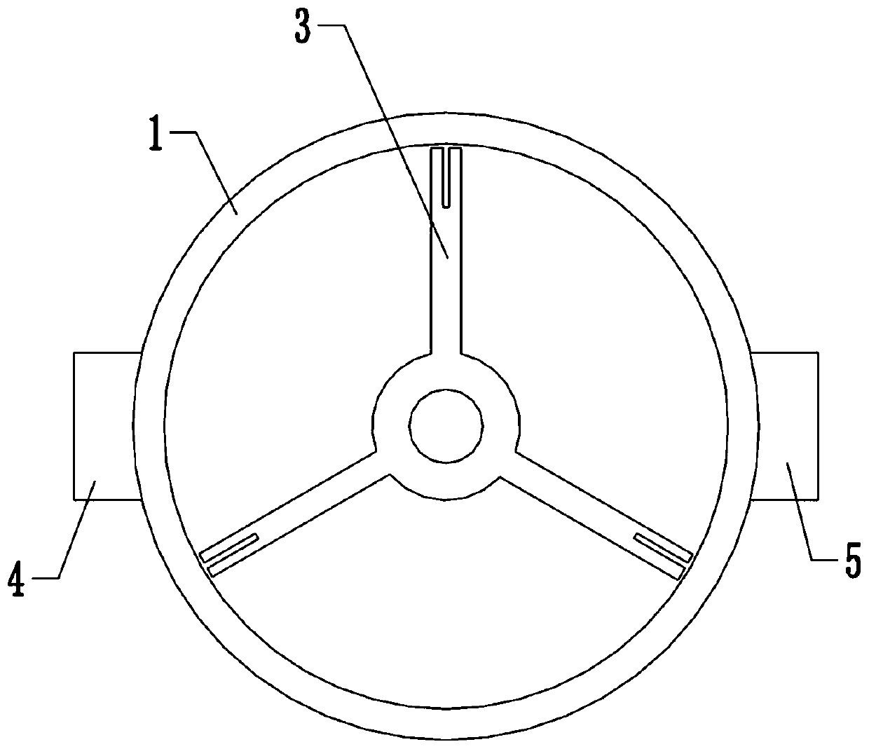
The invention provides a drainage device, and relates to the technical field of drainage. The drainage device comprises a main body provided with a water passing cavity inside, a fan blade rotatably arranged on the main body and positioned in the water passing cavity, an upper cover for covering the water passing cavity, and a motor assembly for driving the fan blade to rotate. The main body is provided with a water inlet and a water outlet separately communicating with the water passing cavity; the fan blade is provided with multiple blades; the upper cover is provided with a pressure reliefhole for communicating the water passing cavity with the external; and the pressure relief hole corresponds to the water passing cavity, and is sandwiched in a region between the water inlet and the water outlet. The multiple blades divide the water passing cavity into multiple water passing regions; the fan blade rotatably passes through the multiple water passing regions to carry water from thewater inlet to the water outlet; and the flow speed of the water flowing out from the water outlet is accelerated through a mode of improving the kinetic energy of the water, so that the drainage effect is improved.

Description

technical field [0001] The invention relates to the technical field of drainage, in particular to a drainage device. Background technique [0002] At present, the drainage system of buildings mostly relies on gravity, and drains water through a combination of sinks and electric pumps. For example: Chinese patent CN201810348865.5 discloses a drainage system for underground garages, which guides the flow through the water guide tank, and the fixed plate at the upper end of the water inlet tank facilitates the insertion of the cover plate into the interior of the storage cavity through the fixed column, and at the same time absorbs the water through the magnet. The cover plate is limited and fixed, which makes the cover plate easy to disassemble; a guide rod is fixedly installed on the fixed plate, and the telescopic movement of the guide rod makes the water baffle play a telescopic and reciprocating role, so that the cleaning brush provided under the water baffle is The debri...

Claims


Application Information

Patent Timeline
Patent Type & Authority Applications(China)
IPC IPC(8): F04D13/06F04D5/00F04D29/18F04D29/42E03F5/22E04H6/42
CPCE03F5/22E04H6/42F04D5/00F04D13/06F04D29/18F04D29/426
Inventor 谷英杰江安娜林羽程林姜峰
Owner HUAQIAO UNIVERSITY
Why Eureka
Try Eureka