Lipstick inner tube oil injection mechanism

A lipstick and inner tube technology, used in mechanical equipment, engine components, lubricating oil containers, etc., can solve the problems of uneven application, difficult to control the amount of oil applied, and low efficiency of lubricating oil spraying, so as to ensure standardization and prevent backflow. , the effect of flexible painting

Inactive Publication Date: 2020-05-12
GUANGZHOU JINHU AUTOMATION EQUIP CO LTD
View PDF4 Cites 0 Cited by
  • Summary
  • Abstract
  • Description
  • Claims
  • Application Information

AI Technical Summary

Problems solved by technology

[0006] In order to solve the low efficiency of spraying lubricating oil through the lipstick tube in the prior art, the amount of oil applied is difficult to control, the oil injection parameters are uneven, the application is uneven, the automation is not enough, and the oil receiving device is not installed to cause pollution to the environment or pollution to the workbench , increase the cleanup of the workbench by cleaning personnel, and provide a method that can spray oil evenly, control the injection speed and the amount of oil, can reduce costs, and can provide oil injection efficiency, high degree of automation, and prevent nozzle residue. The lubricating oil will drip on the workbench or the lipstick tube, and the oil injection mechanism on the inner wall of the lipstick spiral tube that will not pollute the workbench

Method used


Image

  • Lipstick inner tube oil injection mechanism
  • Lipstick inner tube oil injection mechanism
  • Lipstick inner tube oil injection mechanism

Examples


Embodiment 1

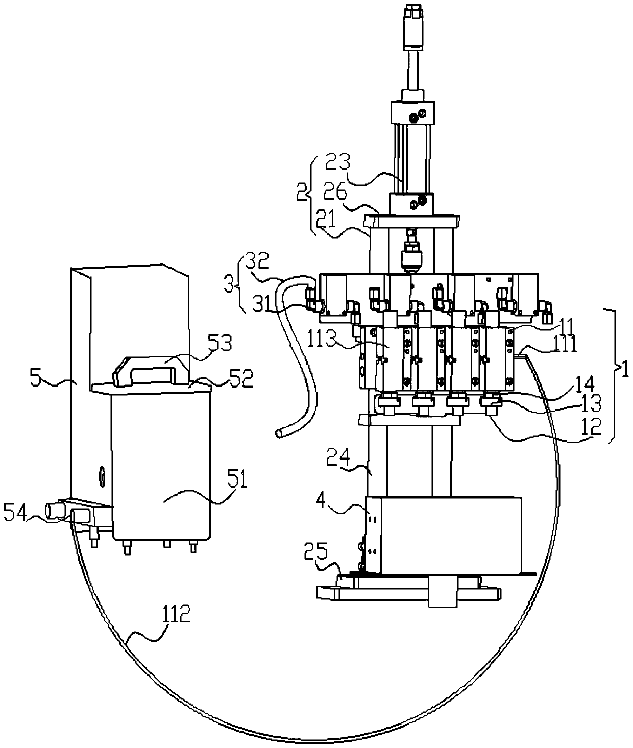
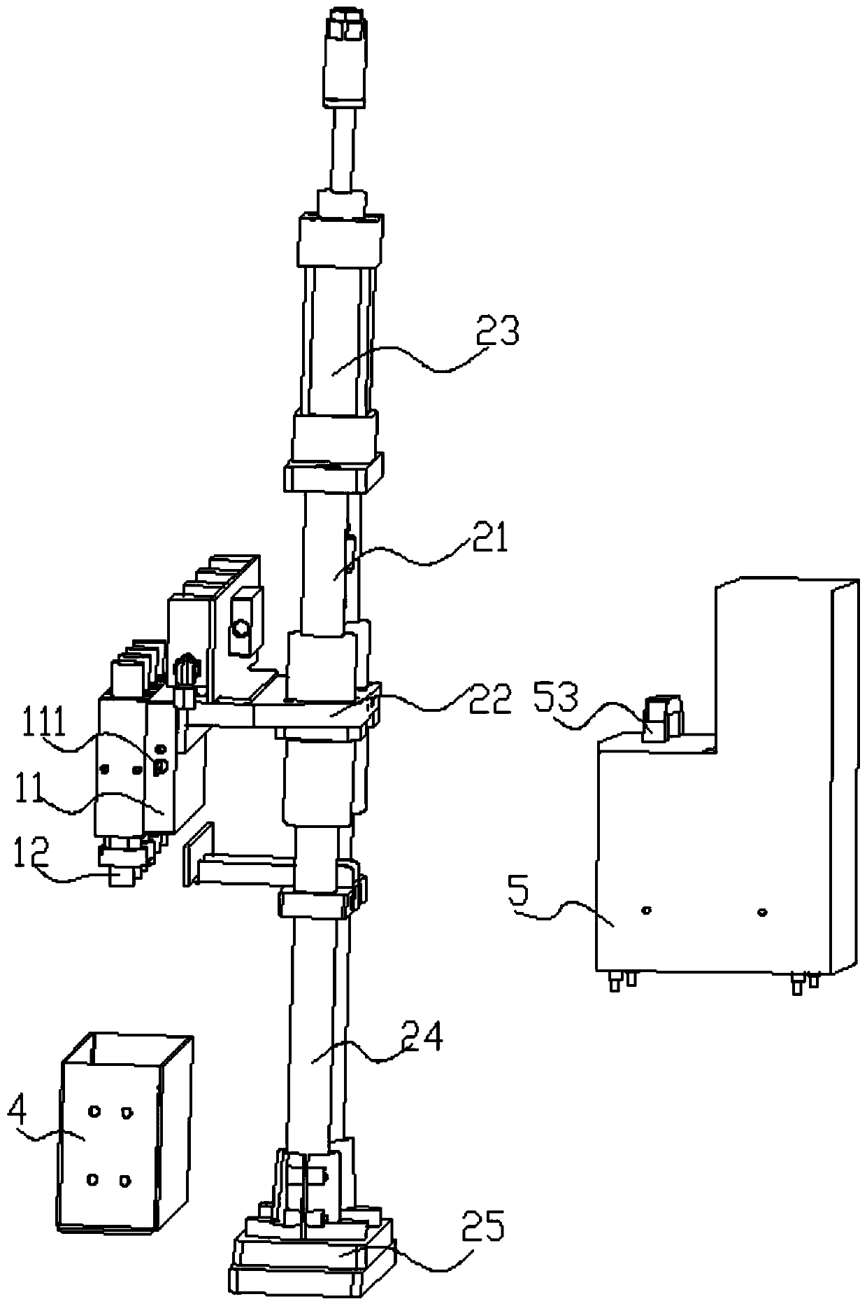
[0047] refer to figure 1 , the oil storage chamber 11 protrudes forward to form four rectangular oil storage compartments 113, the oil storage compartments 113 communicate with the oil storage chamber 11, wherein four nozzles 12 are provided, and the turntable 13 is also provided with four, and driving rod 14 is also provided with four, and each nozzle 12 is all connected with a rotating disc 13, and each rotating disc 13 is all connected with a driving rod 14, and each nozzle 12 top is correspondingly installed with a The oil storage compartment 113 is distributed from the oil in the oil storage compartment 11 to the oil storage compartment 113, and the nozzle 12 sprays oil through the lubricating oil from the oil storage compartment 113 installed above it. One nozzle 12 can spray oil on the inner walls of multiple lipstick spiral tubes at the same time, which improves the work efficiency of oil injection and reduces the cost;

[0048] The oil storage chamber 11 is provided ...

Embodiment 2

[0050] The structure about the nozzle 12 assembly can be:

[0051] The outer end of the nozzle 12 can be surrounded by a cushion material, and the cushion material can be a sponge cushion. When the cushion material is absorbed by the surrounding cushion material, when the cushion material extends into the lipstick spiral tube along with the nozzle 12, the drive rod 14 drives the turntable 13 to drive the nozzle 12 to rotate, so that the cushion material is squeezed, so that the cushion material and the lipstick spiral The inner wall of the tube fits snugly, so that the upper lubricating oil seeps out of the cushion substance and spreads evenly on the inner wall of the lipstick spiral tube.


PUM


Abstract

The invention discloses a lipstick inner tube oil injection mechanism. The lipstick inner tube oil injection mechanism comprises an oil injection assembly and a lifting assembly used for controlling the oil injection assembly to rise and drop. The lifting assembly is located above the oil injection assembly and connected with the oil injection assembly. The oil injection assembly comprises an oilstorage accommodating chamber. The oil storage accommodating chamber is located on one side of the lifting assembly and connected with the lifting assembly. The lifting assembly rises and drops through the oil storage accommodating chamber to realize rising and dropping of the oil injection assembly. A control assembly used for controlling the oil injection speed and flow of the oil injection assembly is arranged above the oil storage accommodating chamber. The control assembly is connected with the oil injection assembly. The lipstick inner tube oil injection mechanism provided by the invention provided by the invention can inject oil uniformly, control the oil injection speed and the oil injection flow, can reduce the cost and improve the oil injection efficiency and is high in automation degree and capable of preventing residual lubricating oil on a spray head from dripping to a working platform or lipstick inner tubes and preventing the working platform from being contaminated.

Description

technical field [0001] The invention belongs to the technical field of oil spray coating, and in particular relates to an oil spray mechanism for spraying oil and lubricating the inner wall of a lipstick spiral tube. Background technique [0002] The lipstick tube is a tube used to hold lipstick. The lipstick tube in the prior art is rotary, easy to use, and rotates out the paste when needed; when not in use, store the paste inside the tube, which can also Avoid contamination of lipstick paste and avoid contamination of clothing. [0003] In the process of making the existing lipstick tube, in order to facilitate the unscrewing of the lipstick tube, it is necessary to spray lubricating oil on the inner wall of the lipstick spiral tube. The existing lipstick spiral tube oil spraying is generally manually coated with lubricating oil with a cotton swab. Then apply it, or spray it manually with a machine. Although manual smearing will be relatively uniform, there are some shor...

Claims


Application Information

Patent Timeline
Patent Type & Authority Applications(China)
IPC IPC(8): F16N7/30F16N19/00F16N23/00F16N31/02
CPCF16N7/30F16N19/00F16N23/00F16N31/02F16N2270/20
Inventor 李鑫辉尹啟华李成宗
Owner GUANGZHOU JINHU AUTOMATION EQUIP CO LTD
Why Eureka
Try Eureka