
Heat exchanger core structure

A heat exchange structure and heat exchanger technology, which are applied to household heating, heating methods, solid heating fuels, etc., can solve the problems of low heat energy utilization efficiency, low space utilization efficiency, inconvenient air circulation, etc. The effect of improving the comfort of use, space utilization efficiency, waste heat utilization efficiency, and space utilization efficiency

Inactive Publication Date: 2020-05-12
杭州翼兔网络科技有限公司
View PDF0 Cites 0 Cited by
  • Summary
  • Abstract
  • Description
  • Claims
  • Application Information

AI Technical Summary

Problems solved by technology

[0003] However, the traditional coal briquette heating kettle has a small heat transfer area during the heating process of the water source inside the kettle, and it is necessary to completely remove the top briquettes to operate when replacing the bottom briquettes. The operation flexibility is poor, and it is easy to cause A lot of heat is wasted. When the water source inside the kettle is heated, it needs to be dumped to take out the water source inside the kettle. The space utilization efficiency in the horizontal direction is low, and it is time-consuming and labor-intensive. The use comfort is low, and the heat energy utilization efficiency of the kettle smoke outlet Low, the inner side wall of the kettle is easy to stick dust, which affects the heat exchange efficiency, and it is not convenient to promote the air circulation inside the heat exchanger core inside the kettle, so that the temperature cannot be raised quickly after replacing the new briquettes

Method used


Image

  • Heat exchanger core structure
  • Heat exchanger core structure
  • Heat exchanger core structure

Examples


Embodiment Construction

[0028] In order to make the technical means, creative features, goals and effects achieved by the present invention easy to understand, the present invention will be further described below in conjunction with specific embodiments.

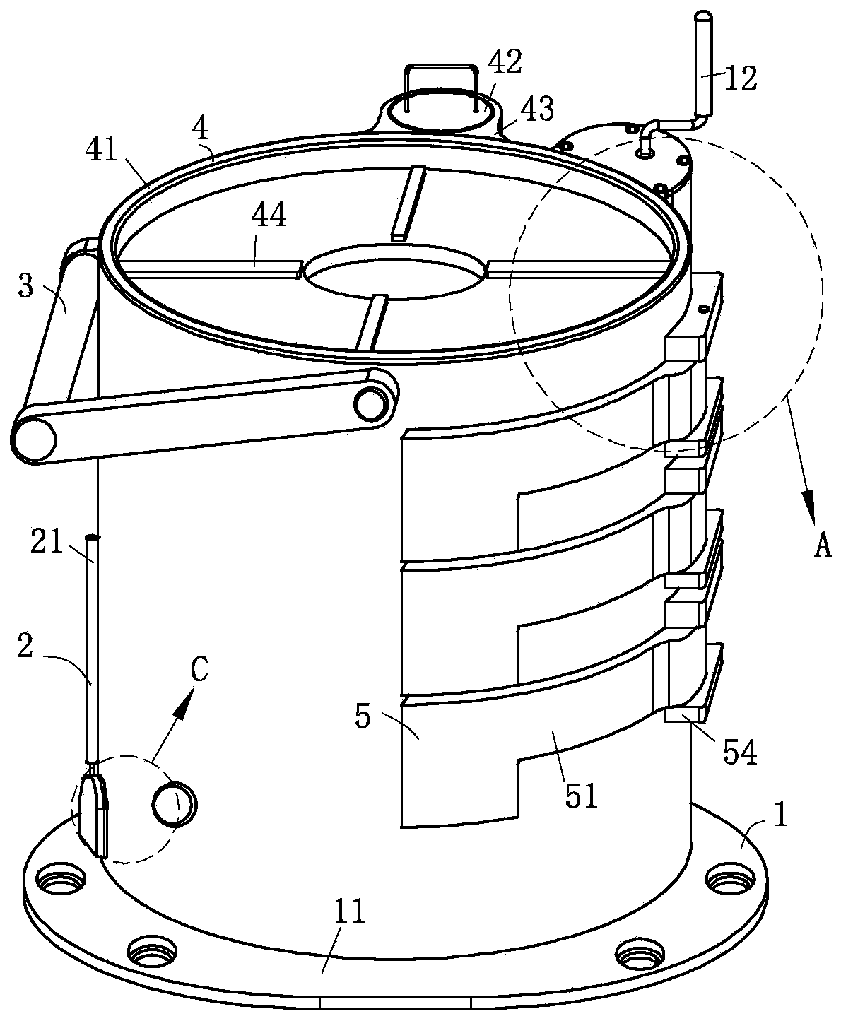
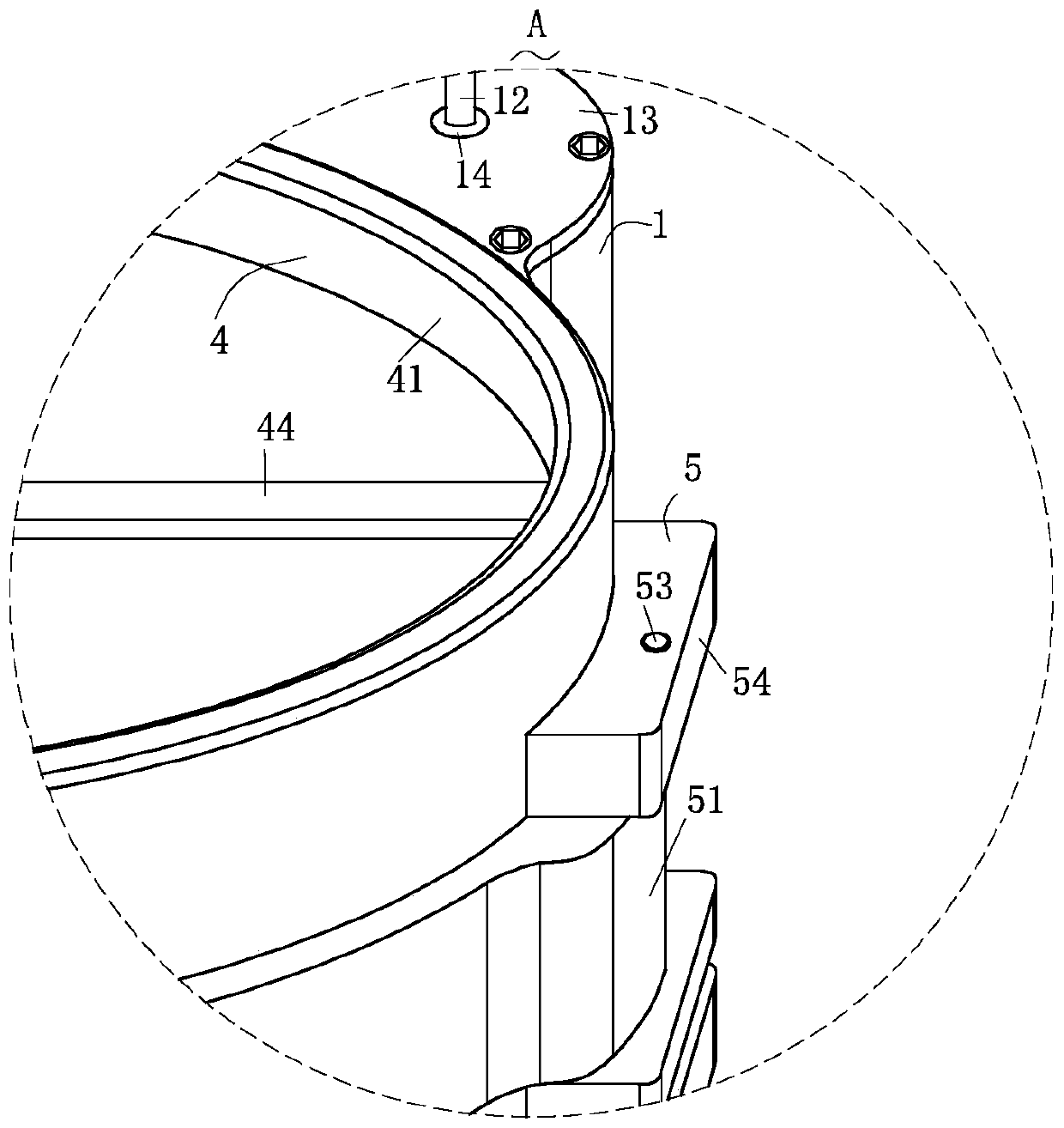
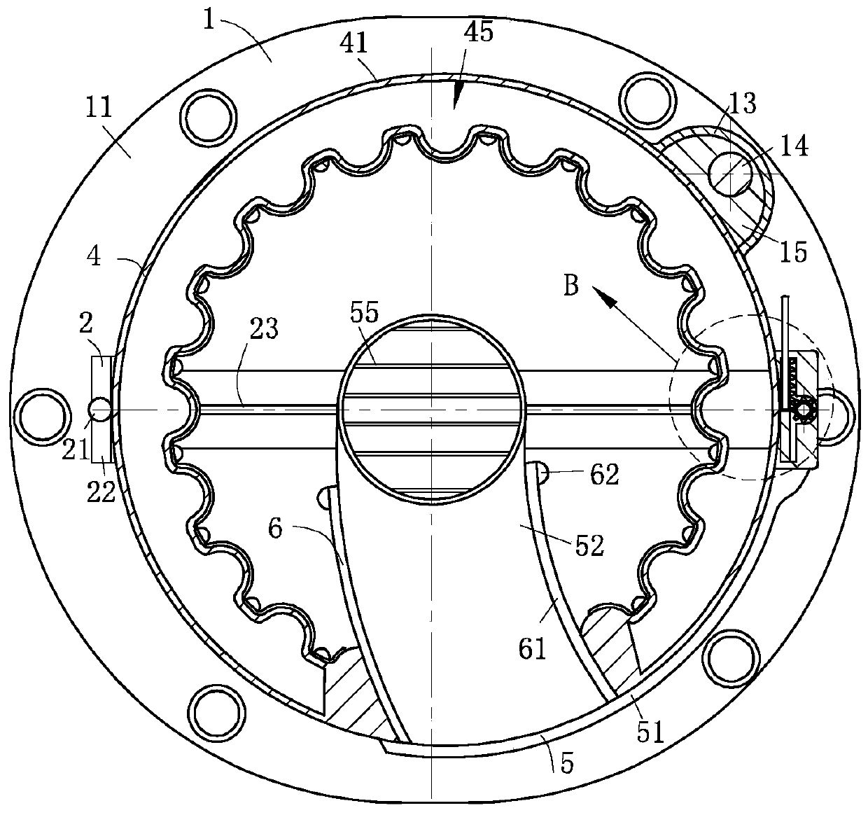
[0029] Such as Figure 1-Figure 7 As shown, a heat exchanger core structure according to the present invention includes a support structure 1, a damper structure 2, a handle 3, a heat exchange structure 4, a storage structure 5, a storage structure 6, a cleaning structure 7 and a pressurization structure 8. The handle 3 is fixed to the heat exchange structure 4 for exchanging heat with the water source by using the hot air flow of coal briquettes, and the support structure 1 for adjusting the height of the heat exchange structure 4 is fixed to the The heat exchange structure 4; the inside of the heat exchange structure 4 is provided with a plurality of storage structures 5 for classifying and storing coal briquettes, and the storage structures 5 a...


PUM


Abstract

The invention relates to heat exchangers, in particular to a heat exchanger core structure. The heat exchanger core structure comprises a support structure, an air door structure, a handle, a heat exchange structure, gathering structures, storage structures, clearing structures and supercharging structures, wherein the support structure is arranged on the heat exchange structure for heat exchangefor a water source through airflow produced by burning of coal briquettes, the heat exchange area is increased by means of the heat exchange structure, so that the heat exchange effect is better; theheight of the heat exchange structure is convenient to adjust by means of the support structure, the water source in the heat exchange structure can be completely discharged under the action of gravity, and the use comfort and space utilization efficiency are greatly improved; a plurality of gathering structures for storing coal briquettes in a classified manner are arranged on the heat exchange structure, the coal briquettes in any position in the heat exchange structure are convenient to replace, heat waste is reduced, and replacement of the coal briquettes is more convenient and rapider; and besides, air circulation between two adjacent coal briquettes is promoted, the burning effect is better, and chips of the coal briquettes are more convenient and rapider to store by cooperation withthe storage structures.

Description

technical field [0001] The invention relates to the technical field of heat exchangers, in particular to a heat exchanger core structure. Background technique [0002] Heat exchanger is a device that transfers part of the heat of hot fluid to cold fluid, also known as heat exchanger; heat exchanger plays an important role in chemical, petroleum, power, food and many other industrial productions; it plays an important role in chemical production Heat exchangers can be used as heaters, coolers, condensers, evaporators and reboilers, etc. For example, heat exchangers are also used to heat water sources in catering, and the hot air flow generated by coal briquettes is used to heat kettles. The kettle is The heat exchanger core structure heats the internal water source. [0003] However, the traditional coal briquette heating kettle has a small heat transfer area during the heating process of the water source inside the kettle, and it is necessary to completely remove the top br...

Claims


Application Information

Patent Timeline
IPC IPC(8): F24B1/182F24B1/183F24B1/191F28G1/08A47J36/26
CPCA47J36/26F24B1/182F24B1/183F24B1/191F28G1/08
Inventor 徐承迪
Owner 杭州翼兔网络科技有限公司
Learn More