Natural accumulator for fuel oil, fuel gas, electric energy and thermal power

An accumulator and thermal technology, which is applied in the field of fuel gas, electric energy and thermal natural accumulators, can solve the problems of reducing the effective utilization rate of energy, deterioration of medium heat storage conditions, and affecting heat exchange efficiency, so as to improve the effective utilization rate of heat, exchange Thermal efficiency increase, effect of improving heating efficiency

Active Publication Date: 2020-05-12
酒泉市方圆锅炉有限公司
View PDF6 Cites 0 Cited by
  • Summary
  • Abstract
  • Description
  • Claims
  • Application Information

AI Technical Summary

Problems solved by technology

At present, when energy-consuming equipment such as fuel oil, gas, and electric energy are used for heating, due to the shortcomings of unlimited energy consumption and limited utilization in the heat transfer and heat exchange processes, a large amount of heat is lost to the air during the heat conduction process, resulting in medium heat storage conditions. Poor, heat storage time is long, need to consume a lot of energy to meet the heat demand of the heating medium, affect the heat exchange efficiency, reduce the effective utilization of energy

Method used


Image

  • Natural accumulator for fuel oil, fuel gas, electric energy and thermal power
  • Natural accumulator for fuel oil, fuel gas, electric energy and thermal power

Examples


Embodiment Construction

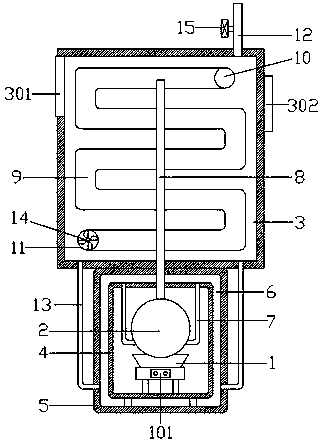
[0018] Such as figure 1 As shown, a fuel gas electric energy thermal natural accumulator includes a thermal energy converter 1, a high-temperature thermal receiving container 2 and a heat storage tank 3, and the thermal energy converter 1 is set as an oil furnace, a gas furnace or an electric furnace, and is equipped with a control switch to control 101, the upper part of the thermal energy converter 1 is provided with a high-temperature thermal receiving container 2, and the high-temperature thermal receiving container 2 is sealed with the outer side of the thermal energy converter 1, and a medium-temperature thermal receiving liner 4 is arranged; the medium-temperature thermal receiving liner 4 is on the outer side There is a medium-temperature heat-receiving outer container 5, and a heat-conducting medium chamber 6 is set between the medium-temperature heat-receiving outer container 5 and the medium-temperature heat-receiving inner container 4; The return pipes 7 are respec...


PUM


Abstract

The invention relates to a natural accumulator for fuel oil, fuel gas, electric energy and thermal power. The natural accumulator comprises a heat energy converter, a high-temperature thermal power receiving container and a heat storage box, the high-temperature thermal power receiving container is arranged on the upper part of the heat energy converter, and a medium-temperature thermal power receiving inner container is arranged on the outer side of the high-temperature thermal power receiving container and the outer side of the heat energy converter in a sealed mode; a medium-temperature thermal power receiving outer container is arranged on the outer side of the medium-temperature thermal power receiving inner container, and a heat-conducting medium cavity is formed between the medium-temperature thermal power receiving outer container and the medium-temperature thermal power receiving inner container; the heat storage box is arranged at the upper part of the medium-temperature thermal power receiving outer container; a thermal conduit is arranged in the middle in the heat storage box and is in communication with the high-temperature thermal power receiving container; an snake-shaped heat dissipation air pipe is arranged in the heat storage box, an air outlet is formed in the upper end of the snake-shaped heat dissipation air pipe, and an air inlet is formed in the lower endof the snake-shaped heat dissipation air pipe; and the bottom of the heat storage box is connected with a circulating water pipe to be in communication with the medium-temperature thermal power receiving outer container. According to the natural accumulator for fuel oil, fuel gas, electric energy and thermal power, heat loss is reduced, the heat storage time is shortened, the heating efficiency is improved, the heat exchange effect is improved, and the effective heat utilization rate is increased.

Description

technical field [0001] The invention relates to the technical field of energy heat utilization, in particular to a fuel gas electric energy heat natural accumulator. Background technique [0002] A heat exchanger is an energy-saving device that transfers heat between materials between two or more fluids at different temperatures. It is one of the essential facilities for domestic heating, especially as the method gradually changes from coal to oil, With the development of coal-to-gas and coal-to-electricity, individual heating energy-consuming equipment is gradually replaced by oil-fired boilers, gas-fired boilers, electric boilers, etc., and the purpose of heating is achieved through heating-heat transfer-radiation. At present, when energy-consuming equipment such as fuel oil, gas, and electric energy are used for heating, due to the shortcomings of unlimited energy consumption and limited utilization in the heat transfer and heat exchange processes, a large amount of heat ...

Claims


Application Information

Patent Timeline
Patent Type & Authority Applications(China)
IPC IPC(8): F28D20/00F28F27/00F24F5/00
CPCF24F5/0017F24F2005/0025F28D20/0034F28D2020/0078F28F27/00Y02E60/14
Inventor 任建忠谢振斌于东升
Owner 酒泉市方圆锅炉有限公司
Why Eureka
Try Eureka