
Terminal having reconfigurable antenna

A technology for reconstructing antennas and terminals, which is applied to antenna equipment, antennas, and antenna components with additional functions. It can solve the problems of narrow headroom and the inability of headroom to meet space requirements, and achieve the effect of meeting omnidirectional requirements.

Active Publication Date: 2020-05-12
QINGDAO HISENSE MOBILE COMM TECH CO LTD
View PDF4 Cites 2 Cited by
  • Summary
  • Abstract
  • Description
  • Claims
  • Application Information

AI Technical Summary

Problems solved by technology

However, affected by the development trend of all-metal materials and high-screen ratio of mobile communication terminals such as mobile phones, the clearance area for installing antennas in mobile communication terminals such as mobile phones will become narrower and narrower.
The increasingly narrow clearance area cannot meet the space requirements of the existing architecture antenna to change the antenna direction by changing the antenna routing

Method used


Image

  • Terminal having reconfigurable antenna
  • Terminal having reconfigurable antenna
  • Terminal having reconfigurable antenna

Examples


Embodiment Construction

[0018] In order to make the object, technical solution and advantages of the present invention clearer, the present invention will be further described in detail below in conjunction with the accompanying drawings and embodiments. It should be understood that the specific embodiments described here are only used to explain the present invention, not to limit the present invention.

[0019] The terminal with a reconfigurable antenna provided in the embodiment of the present application includes a terminal with a metal frame such as a mobile phone and a PC. For ease of description, the mobile phone is taken as an example below to describe the embodiment of the present application in detail.

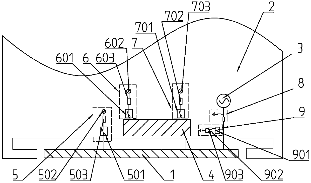
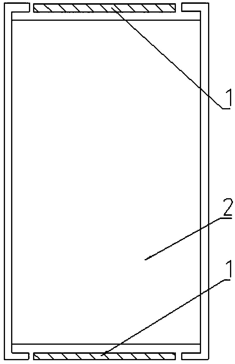
[0020] as attached figure 1 As shown, the terminal with a reconfigurable antenna provided by the embodiment of the present application includes a non-grounded metal frame 1, an alloy base plate 2, a feed source 3, a suspended metal body 4, a first ground circuit 5, and a second ground circ...


PUM


Abstract

The invention provides a terminal with a reconfigurable antenna. The terminal comprises a non-grounding metal frame, an alloy bottom plate, a feed source, a suspension metal body, a first grounding circuit and a second grounding circuit, wherein the feed source is connected with the non-grounding metal frame, the non-grounding metal frame is connected with the suspension metal body, the suspensionmetal body serves as a suspension reference ground, the first grounding circuit comprises a first control switch and a first grounding point, the first signal end of the first control switch is connected with the non-grounding metal frame, the second signal end of the first control switch is connected with the first grounding point, the first grounding point is used for connecting the alloy bottom plate, the second grounding circuit comprises a second control switch and a second grounding point, the first signal end of the second control switch is connected with the suspension metal body, thesecond signal end of the second control switch is connected with the second grounding point, and the second grounding point is used for connecting the alloy bottom plate. According to the terminal provided by the invention, the reconstruction of the antenna radiation direction in the narrower and narrower trend of the clearance zone is realized, and the omnidirectional requirement of the antennain the terminal can be met.

Description

technical field [0001] The present application relates to the technical field of communication equipment, and in particular to a terminal with a reconfigurable antenna. Background technique [0002] With the development of smart mobile terminal technology, mobile communication terminals such as mobile phones carry more and more information transmission functions, and one-to-many link scenarios of a single communication terminal are also very common, such as mobile phones and multiple base stations, positioning devices and multiple Satellites, routing equipment and multiple data terminals, etc. Therefore, in order to adapt to the above-mentioned usage scenarios of mobile communication terminals such as mobile phones, mobile communication terminals such as mobile phones have higher and higher requirements on the omnidirectionality of their antennas. [0003] As we all know, the antenna is a kind of converter, which converts the guided wave propagating on the transmission line...

Claims


Application Information

Patent Timeline
IPC IPC(8): H01Q1/36H01Q1/44H01Q1/48H01Q3/00H01Q5/10H01Q5/20H01Q5/50H01Q1/24H01Q1/22
CPCH01Q1/36H01Q1/44H01Q1/48H01Q3/00H01Q5/10H01Q5/20H01Q5/50H01Q1/242H01Q1/2258Y02D30/70
Inventor 王剑胡育根
Owner QINGDAO HISENSE MOBILE COMM TECH CO LTD
Learn More