Radio-over-fiber switching system

A technology of switching system and wireless switch, applied in the field of optical carrier wireless switching system, can solve the problems of increasing the radiation power of WiFi equipment, inconvenient communication capacity allocation and reconstruction, etc., to achieve the effect of hybrid transmission

Inactive Publication Date: 2012-09-12
广州飞瑞敖电子科技股份有限公司
View PDF3 Cites 15 Cited by
  • Summary
  • Abstract
  • Description
  • Claims
  • Application Information

AI Technical Summary

Problems solved by technology

[0004] However, increasing the radiation power of WiFi devices has certain disadvantages, because WiFi devices use the ISM operating frequency band, which itself limits the increase in radiation power, so the method of increasing the radiation power of WiFi devices and expanding the coverage of WiFi signals is adopted Inadequate
[0005] At the same time, in the network deployment method of the prior art, the communication capacity of the remote access point is fixed, so it is inconvenient to allocate and reconfigure the communication capacity

Method used


Image

  • Radio-over-fiber switching system
  • Radio-over-fiber switching system
  • Radio-over-fiber switching system

Examples


Embodiment Construction

[0016] The present invention will be further described below in conjunction with the accompanying drawings and embodiments.

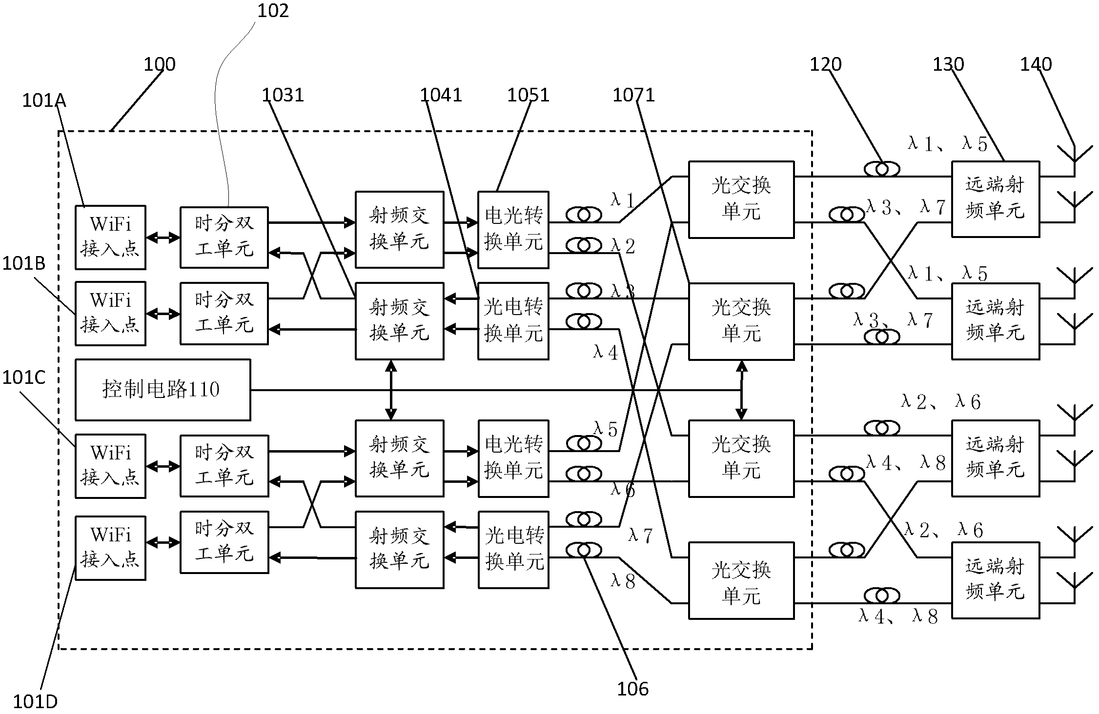
[0017] refer to figure 1 , according to an embodiment of the present invention, a wireless-over-fiber switching system includes: a wireless-over-fiber switch 100, a remote radio frequency unit 130, and an analog device for transmitting signals between the wireless-over-fiber switch 100 and the remote radio frequency unit 130 The optical fiber line 120 and the radiation antenna 140 connected with the remote radio frequency unit 130 .

[0018] The wireless over optical switch 100 includes: at least four WiFi access points 101A-101D for transmitting and receiving WiFi radio frequency signals, and for connecting WiFi access points 101A-101D from or to WiFi access points 101A-101D A time division duplex unit 102 for transmitting and receiving separated radio frequency signals, a radio frequency switching unit 1031 for switching and distributing WiFi radio f...


PUM


Abstract

A radio-over-fiber switching system comprises a radio-over-fiber switch, remote radiofrequency units, analog optical fiber circuits and radiating antennas, signals are transmitted between radio-over-fiber switch and the remote radiofrequency units by the analog optical fiber circuits, and the radiating antennas are connected with the remote radiofrequency units. The radio-over-fiber switch consists of at least four WiFi (wireless fidelity) access points, time division duplex units, radiofrequency switch units, at least two electronic-to-optical conversion units, optical switch units and a control circuit, the WiFi access points are used for receiving and transmitting WiFi radiofrequency signals, the time division duplex units are used for receiving, transmitting and separating the WiFi radiofrequency signals which are transmitted from or to the WiFi access points, the radiofrequency switch units are used for switching and distributing the WiFi radiofrequency signals, the electronic-to-optical conversion units are used for converting the WiFi radiofrequency signals from the radiofrequency switch units into optical signals, the optical switch units are used for switching and distributing the optical signals, and the control circuit is used for controlling at least two photoelectric conversion units which are used for converting the optical signals from the optical switch units into WiFi radiofrequency signals and controlling the radiofrequency switch units and the optical switch units.

Description

【Technical field】 [0001] The invention relates to an optical-carrying wireless switching system. 【technical background】 [0002] At present, WiFi wireless local area network is becoming more and more popular, and has become the first choice for establishing a wireless local area network. But the signal coverage range of a common WiFi access point is: about 50-100 meters indoors; about 100-150 meters outdoors. [0003] In order to expand the coverage of WiFi signals, the main methods currently adopted by the industry include: increasing the radiation power of WiFi devices. [0004] However, increasing the radiation power of WiFi devices has certain disadvantages, because WiFi devices use the ISM operating frequency band, which itself limits the increase in radiation power, so the method of increasing the radiation power of WiFi devices and expanding the coverage of WiFi signals is adopted Inadequate. [0005] Meanwhile, in the network deployment method in the prior art, th...

Claims


Application Information

Patent Timeline
Patent Type & Authority Applications(China)
IPC IPC(8): H04B10/12H04W88/08H04B10/2575
Inventor 庞文凤孟学军梅仲豪
Owner 广州飞瑞敖电子科技股份有限公司
Why Eureka
Try Eureka