Mining imaging device, equipment and method
An imaging device and mine-used technology, which is applied in image communication, TV, color TV parts, etc., can solve the problem that visible light cameras and visible light supplementary lights cannot satisfy the clear imaging of real scenes in mines, and reduce the risk of accidents Probability, small size, and the effect of increasing the shooting distance
- Summary
- Abstract
- Description
- Claims
- Application Information
AI Technical Summary
Problems solved by technology
Method used
Image

Examples
Embodiment 1
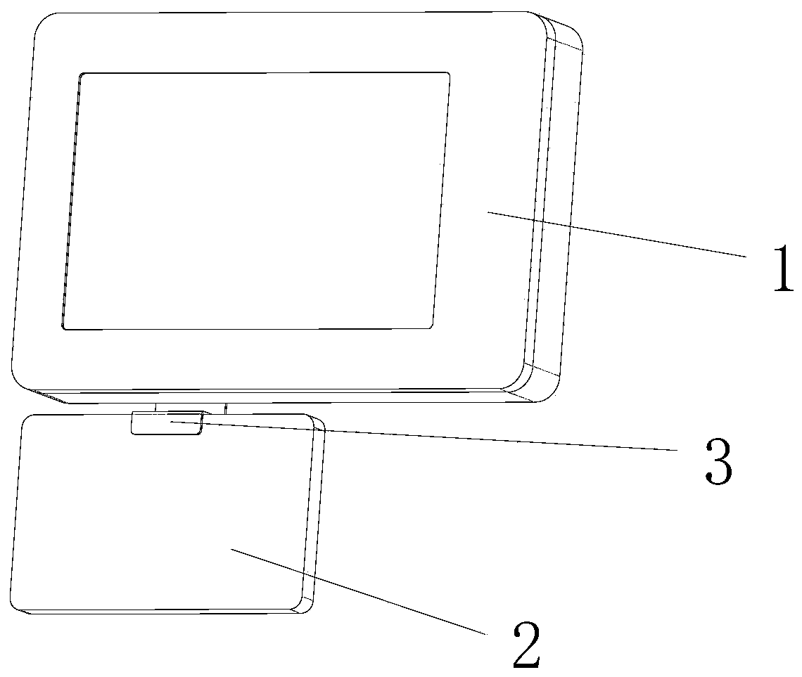
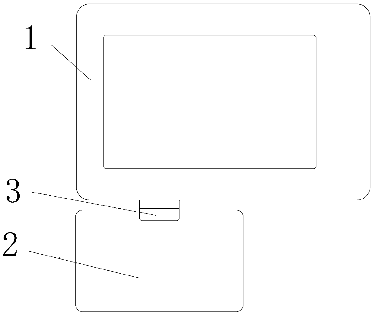
[0054] Such as figure 1 As shown, a mining imaging device includes an imaging module 1 and a supplementary light 2 for providing infrared light and visible light to the imaging module 1;
[0055] In this embodiment, the supplementary light 2 is installed on the imaging module 1 through the bracket 3; without the bracket 3, the supplementary light 2 can also be held directly or fixed in other ways.
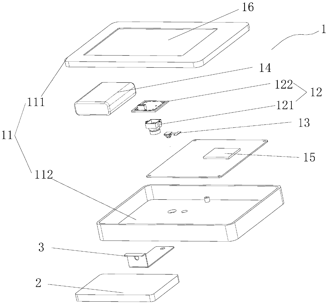
[0056] Such as figure 2 As shown, the imaging module 1 includes a housing 11 with a cavity, a characteristic spectrum camera 12, a zoom camera 13, a power supply 14, a processor 15, and a display screen 16; the zoom camera in this embodiment is a high-definition zoom camera 13, and the characteristic spectrum The camera 12 and the high-definition zoom camera 13 are all installed on one side of the housing 11, the display screen 16 is installed on the other side of the housing 11, the processor 15 and the power supply 14 are installed inside the housing 11, and the characteristic ...
Embodiment 2
[0071] Such as figure 2 , Figure 5 As shown, the difference between this embodiment and Embodiment 1 is that the bracket 3 is a Z-shaped bracket, the bracket 3 has a connection hole, the fill light 2 is connected to one end of the bracket 3 through bolts or screws, and the imaging The module 1 is connected to the other end of the bracket 3 through bolts or screws.
[0072] In this embodiment, the fill light 2 is installed under the imaging module 1 . Therefore, the detachable connection between the supplementary light 2 and the imaging module 1 is realized, which is convenient for replacement. In addition, other detachable installation methods can be applied here.
Embodiment 3
[0074] An imaging method using the mine imaging device in the first and second embodiments above comprises the following steps:
[0075] S1: Fix the imaging module 1 and the fill light 2 through the bracket 3, turn on the imaging module 1 and the fill light 2 respectively, the processor 15 has a Bluetooth module that can be paired with the fill light 2, and connect the fill light 2 and the imaging module 1 to achieve wireless connection;
[0076] S2: The imaging module 1 obtains the optimal fill light parameters, and the imaging module 1 sends the obtained optimal fill light parameters to the fill light 2;
[0077] The specific steps for the imaging module to obtain the optimal fill light parameters include:
[0078] S21: The supplementary light 2 has at least 3 different supplementary light parameters in advance, turn on the light source of the supplementary light, click the pre-shooting button of the imaging module 1 to take pictures of the target object, and the imaging mo...
PUM
| Property | Measurement | Unit |
|---|---|---|
| Center wavelength | aaaaa | aaaaa |
Abstract
Description
Claims
Application Information
 - R&D
- Intellectual Property
- Life Sciences
- Materials
- Tech Scout
- Unparalleled Data Quality
- Higher Quality Content
- 60% Fewer Hallucinations
Browse by: Latest US Patents, China's latest patents, Technical Efficacy Thesaurus, Application Domain, Technology Topic, Popular Technical Reports.
© 2025 PatSnap. All rights reserved.Legal|Privacy policy|Modern Slavery Act Transparency Statement|Sitemap|About US| Contact US: help@patsnap.com