Stirrer for continuously mixing oily fluid

A stirrer and fluid technology, applied in the direction of mixers, mixer accessories, mixers with rotating stirring devices, etc., can solve the problems of unstable stirring transmission efficiency, uneven mixing of oily fluids, etc., to improve convenience and stability , The effect of double transmission is stable, and the effect of guiding effect is realized

Inactive Publication Date: 2020-05-15
丁许
View PDF6 Cites 3 Cited by
  • Summary
  • Abstract
  • Description
  • Claims
  • Application Information

AI Technical Summary

Problems solved by technology

[0003] There are some deficiencies in the use of existing agitators. For example, when two or more oily fluids are mixed, due to the weak repulsion between the oily fluids, continuous three-dimensional stirring cannot be effectively performed. , it is easy to cause uneven mixing between oily fluids, and the existing stirring transmission efficiency is unstable

Method used


Image

  • Stirrer for continuously mixing oily fluid
  • Stirrer for continuously mixing oily fluid
  • Stirrer for continuously mixing oily fluid

Examples


Embodiment 1

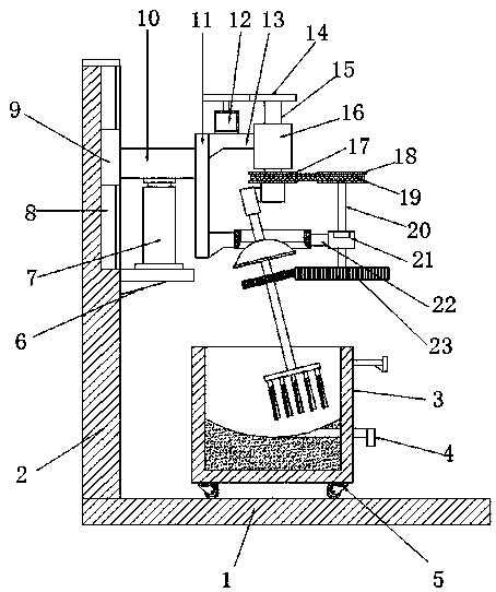
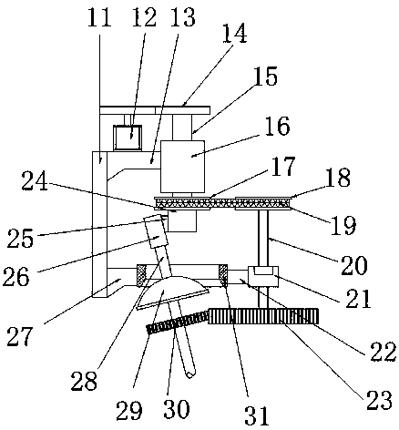
[0028] refer to Figure 1-3 , an agitator for continuous mixing of oily fluids, comprising a bottom plate 1, a side plate 2 is fixed on the left side of the top outer wall of the bottom plate 1, a lifting mechanism is fixed on the outer wall of one side of the side plate 2, and the lifting mechanism is fixedly connected with a connecting plate 11, and the connecting plate 11 One side is fixed with the first connecting block 13 and the second connecting block 27, the first connecting block 13 is fixedly connected with the axle sleeve 16, the rotating shaft 15 is plugged in the axle sleeve 16, the top of the rotating shaft 15 is connected with the drive mechanism, and the rotating shaft 15 bottom ends are fixed with driving block 24, and driving block 24 sides are fixed with wedge-shaped block 25, and the slope of wedge-shaped block 25 is fixed with fixed shaft 26, and the bottom end of fixed shaft 26 is rotated and installed with stirring shaft 28, and the bottom end of stirring...

Embodiment 2

[0036] refer to Figure 4 , an agitator for continuous mixing of oily fluids. The difference between this embodiment and Embodiment 1 is that the moving wheel 5 is replaced by a slider 35, and two slide rails 34 are fixed on the bottom plate 1, and the slider 35 is slidably engaged on the slider. on track 34.

[0037] The working principle of this embodiment: the slide rail 34 can facilitate the lateral movement of the mixing box 3 by using the slider 35, realize the guiding effect of the mixing box 3 moving, and improve the convenience and stability of the mixing box 3 movement.


PUM


Abstract

The invention discloses a stirrer for continuously mixing oily fluid. The stirrer comprises a bottom plate, and a side plate is fixed to the left side of the outer wall of the top of the bottom plate.A lifting mechanism is fixed on the outer wall of one side of the side plate; the lifting mechanism is fixedly connected with a connecting plate; a first connecting block and a second connecting block are fixed on one side of the connecting plate; a shaft sleeve is fixedly connected to the first connecting block; a rotating shaft is rotationally inserted into the shaft sleeve; the top end of therotating shaft is in transmission connection with a driving mechanism, a driving block is fixed to the bottom end of the rotating shaft, a wedge block is fixed to one side of the driving block, a fixing shaft is fixed to the slope of the wedge block, a stirring shaft is fixed to the bottom end of the fixing shaft, a stirring mechanism is fixed to the bottom end of the stirring shaft, a fixing ringis fixed to the second connecting block, and a fixing block is fixed on one side of the fixing ring. Autorotation of the stirring shaft and the stirring mechanism can be achieved, overall rotation ofthe stirring mechanism can be achieved while autorotation is conducted, the stirring and mixing effect is improved, in addition, belt transmission and gear transmission are conducted at the same time, and the double-transmission effect is more stable.

Description

technical field [0001] The invention relates to the technical field of stirring, in particular to a stirrer for continuous mixing of oily fluid. Background technique [0002] The agitator is a device for forced convection and uniform mixing of liquid and gaseous media. The type, size and speed of the stirrer have an effect on the distribution of the stirring power between the bulk flow and the turbulent pulsations. Generally speaking, the power distribution of the turbine agitator is favorable for turbulent flow fluctuations, while the propeller agitator is favorable for the bulk flow. For the same type of agitator, under the condition of the same power consumption, the agitator with large diameter and low rotation speed mainly consumes power in the overall flow, which is conducive to macroscopic mixing. Small-diameter, high-speed stirrer, the power is mainly consumed in turbulent pulsation, which is conducive to micro-mixing. [0003] There are some deficiencies in the u...

Claims


Application Information

Patent Timeline
Patent Type & Authority Applications(China)
IPC IPC(8): B01F7/30B01F15/00
CPCB01F27/213B01F27/191B01F27/95B01F35/50B01F35/42
Inventor 丁许
Owner 丁许
Why Eureka
Try Eureka