A fixture device and clamping method for FMC motor shaft processing

A fixture device and motor shaft technology, which is applied in the field of numerical control, can solve the problems that only horizontal milling machines can be used for non-U-shaped slot milling of ports, and cannot be used for non-U-shaped slot milling of motor shaft parts, so as to achieve stability , Protect the motor shaft and avoid over-clamping effect

Active Publication Date: 2020-09-01
YIBIN VOCATIONAL & TECH COLLEGE
View PDF11 Cites 0 Cited by
  • Summary
  • Abstract
  • Description
  • Claims
  • Application Information

AI Technical Summary

Problems solved by technology

[0004] However, the existing vertical milling machine cannot be suitable for the non-U-shaped groove milling of the port of the motor shaft part due to its fixture characteristics. Therefore, designing a fixture suitable for the motor shaft part processing for the vertical milling machine can solve the problem. After the motor shaft is processed by the turning machining center, the non-U-shaped slot milling of the port can only be done with a horizontal milling machine, so that the vertical milling machine can also cooperate with the turning center to complete the processing of the end face groove, which greatly improves the FMC flexible manufacturing unit. economy

Method used


Image

  • A fixture device and clamping method for FMC motor shaft processing
  • A fixture device and clamping method for FMC motor shaft processing

Examples


Embodiment 1

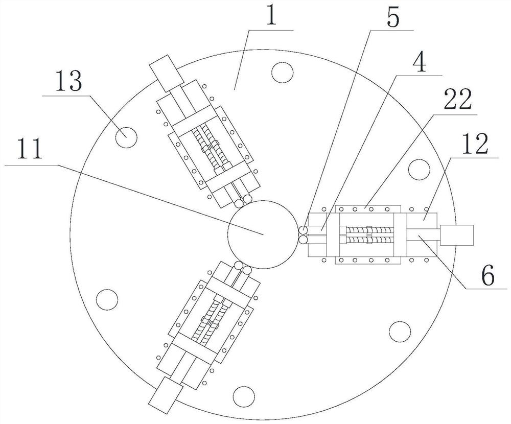
[0041] Such as figure 1 , figure 2 As shown, a fixture device used for FMC motor shaft processing includes a fixed plate 1, and a plurality of mounting holes 13 are arranged on the fixed plate 1. Installed on the workbench of the vertical milling machine, the upper end surface of the fixed disk 1 is provided with a positioning groove 11 at the center, the positioning groove 11 is a circular groove, and the upper end surface of the fixed disk 1 is outside the positioning groove 11 There are three slide grooves 12, the slide grooves 12 are dovetail grooves, the slide grooves 12 are arranged along the radial direction of the fixed disk 1, and the three slide grooves 12 are evenly arranged along the circumferential direction of the fixed disk 1. A clamping plate 2 is arranged in the chute 12, and two clamping rods 4 are arranged at the inner end of the clamping plate 2, and the end of the clamping rods 4 is provided with a limit ball 5 for clamping the motor shaft ; Also includ...

Embodiment 2

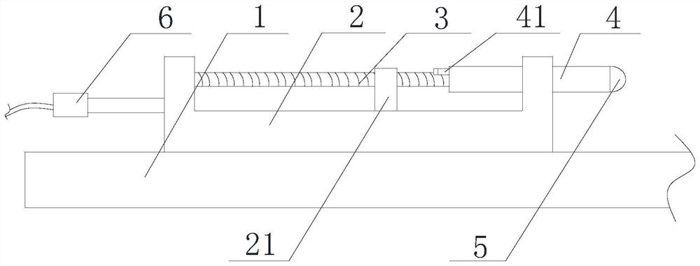
[0045] Such as figure 1 , figure 2 As shown, this embodiment is based on Embodiment 1, the clamping plate 2 is a U-shaped plate, two threaded rods 3 are vertically arranged on one side wall of the U-shaped plate, and two threaded rods 3 are arranged on the other side wall The through hole, the clamping rod 4 is penetrated in the through hole, the clamping rod 4 is a sleeve structure, and the clamping rod 4 is threadedly connected with the end of the threaded rod 3 .

[0046] The working principle of this embodiment is as follows:

[0047] Insert one end of the motor shaft to be processed into the positioning groove 11, so that the end of the motor shaft to be processed faces upward; drive the cylinder 6, so that the clamping plate 2 moves toward the motor shaft in the chute 12, and when the limit ball 5 When the motor shaft is about to be in contact with or just in contact with the motor shaft, the cylinder 6 stops, and the clamping rod 4 is manually adjusted, and the clamp...

Embodiment 3

[0049] Such as figure 1 , figure 2 As shown, this embodiment is based on Embodiment 2, and the end of the clamping rod 4 away from the limit ball 5 is provided with an operating handle 41; the bottom of the U-shaped plate is provided with a support plate 21 for supporting the threaded rod 3; The top of the support plate 21 is provided with an arc-shaped groove.


PUM


Abstract

The invention discloses a clamp device used for FMC motor shaft processing and a clamping method thereof. The clamp device comprises a fixed disc, and further comprises a gas cylinder, wherein a positioning slot is formed in the center of the upper end surface of the fixed disc; three slide slots are formed in positions, outside the positioning slot, of the upper end surface of the fixed disc; theslide slots are formed in a radial direction of the fixed disc; the three slide slots are uniformly formed in the peripheral direction of the fixed disc; clamping plates are arranged in the slide slots; two clamping rods are arranged at inner side ends of the clamping plates; the end parts of the clamping rods are provided with limiting balls for clamping a motor shaft; and a plunger piston of the gas cylinder is connected to the outer side ends of the clamping plates. The clamp device disclosed by the invention is used for realizing milling processing of motor shaft parts through a verticaltype milling machine.

Description

technical field [0001] The invention relates to the technical field of numerical control, in particular to a fixture device and a clamping method for FMC motor shaft processing. Background technique [0002] With the continuous upgrading of the manufacturing industry, the mass production application of flexible manufacturing cells (FMC) in enterprises has become very popular. Whether the process system design of the flexible production line is optimized or not, in addition to whether the flexible manufacturing unit equipment, control system and other equipment meet the requirements, the positioning and clamping fixtures play a very critical role, especially in mass production. [0003] Motor shaft parts are one of the production objects of FMC flexible manufacturing unit. At present, after the motor shaft is processed by the turning machining center, a horizontal milling machine is usually used for milling the non-U-shaped groove of the port, because the horizontal milling ...

Claims


Application Information

Patent Timeline
Patent Type & Authority Patents(China)
IPC IPC(8): B23Q3/08
CPCB23Q3/08
Inventor 张德红黄河门延会毛羽
Owner YIBIN VOCATIONAL & TECH COLLEGE
Why Eureka
Try Eureka