Automatic feeding and distributing device for clamping pieces

A material dividing device and automatic feeding technology, which is applied in the conveyor control device, transportation and packaging, conveyors, etc., can solve the problem that the clip cannot move automatically on demand.

Pending Publication Date: 2020-05-15
LUSHAN COLLEGE OF GUANGXI UNIV OF SCI & TECH
View PDF0 Cites 0 Cited by
  • Summary
  • Abstract
  • Description
  • Claims
  • Application Information

AI Technical Summary

Problems solved by technology

If there is no distributing device for the automatic loading of the clips, the clips will not be able to automatically mo

Method used


Image

  • Automatic feeding and distributing device for clamping pieces
  • Automatic feeding and distributing device for clamping pieces
  • Automatic feeding and distributing device for clamping pieces

Examples


Embodiment Construction

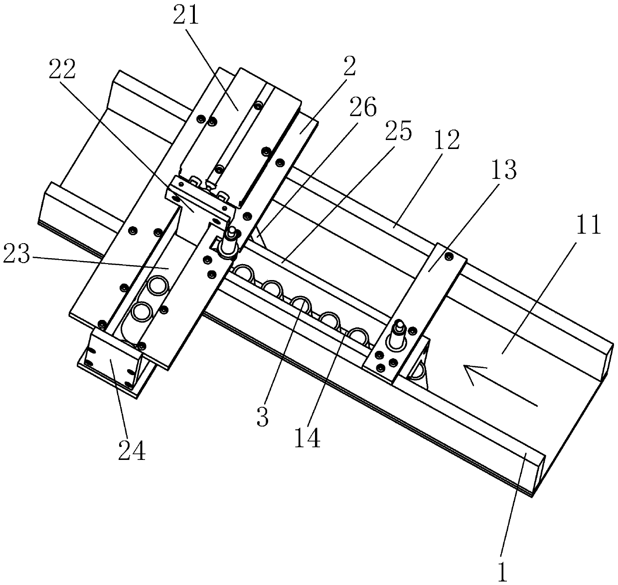
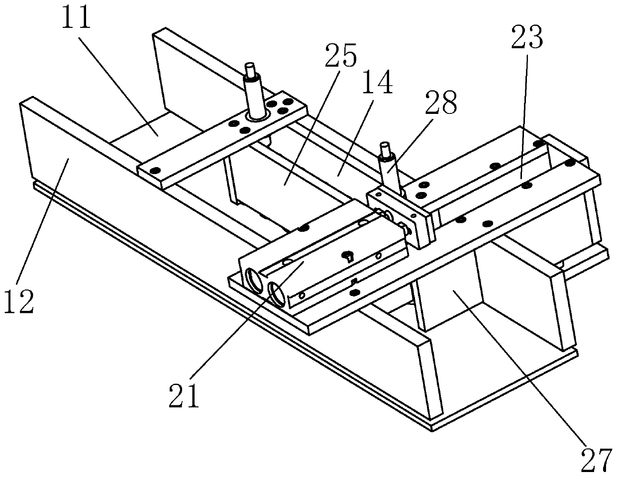
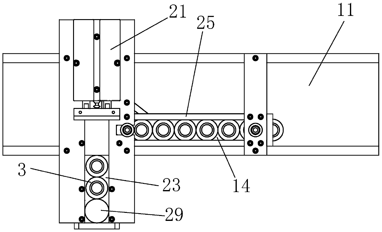
[0018] A clip automatic feeding and distributing device, including a conveying device and a pushing device, the conveying device includes a conveying trough and a conveying line chain plate, the conveying line chain plate is arranged at the bottom of the conveying trough, and the pushing device includes A limiting plate, a pushing plate, a blanking chute, a cylinder and a splitter plate, the blanking trough is arranged on one side of the conveying trough, the limiting plate is arranged in the conveying trough, and the limiting plate is located above the chain plate of the conveying line , that is, there is a gap between the bottom of the limit plate and the chain plate of the transmission line, so that the limit plate will not hinder the transmission of the chain plate of the transmission line. The limit plate and the side wall on one side of the transmission groove form a push groove. The limit plate is fixedly connected with the side wall of the conveying trough through the f...


PUM


Abstract

The invention relates to an automatic feeding and distributing device for clamping pieces. The device comprises a conveying device and a pushing device; the conveying device includes a conveying trough and a conveying line chain plate; the conveying line chain plate is arranged at the bottom part of the conveying though; the pushing device includes a limiting plate, a pushing plate, a dropping trough and an air cylinder; the dropping trough is arranged at one side of the conveying trough; the limiting plate is arranged in the conveying trough; the limiting plate and the side wall of one side of the conveying trough form a pushing trough; a discharge hole is formed in the side wall of the conveying trough; the pushing trough communicates with the dropping trough through the discharge hole;the pushing plate is arranged in the pushing trough; the pushing plate can move towards the dropping trough in the pushing trough; the pushing plate is connected with the air cylinder; the air cylinder is arranged above the conveying trough through a fixed plate; by control of the air cylinder, the pushing plate can push the clamping pieces conveyed into the pushing trough into the dropping trough; and a dropping hole is formed in the bottom part of one end, away from the pushing plate, of the dropping trough. The device can convey the clamping pieces into a discharging pipe one by one, and guarantees machining of the clamping pieces.

Description

technical field [0001] The invention relates to a material distributing device, in particular to an automatic feeding and distributing device for clips. Background technique [0002] Because the clips need to be processed one by one during the processing of the clips, the clips need to be put into the feeding tube one by one. The processing flow of the clip machine mainly goes through the following 9 processes: sawing→forging→turning the cone→turning the end face→punching→grinding the outer cone→tapping thread→sawing the elastic groove→sawing (divided into two even pieces). All these machining processes are completed through the automatic clip conveying line, and there must be an automatic clip feeding device before each process is processed. If there is no distributing device for the automatic feeding of the clips, the clips cannot be automatically moved to the designated position for positioning and clamping of the clips in each process as required and machined. Content...

Claims


Application Information

Patent Timeline
IPC IPC(8): B65G47/82B65G17/06B65G21/20B65G43/08
CPCB65G17/065B65G21/2063B65G43/08B65G47/82B65G2203/042
Inventor 范嘉陈春林邹俊崔志佳常德旺戚艳超王鸿宣国瀚杰黄海添经胜博李昊楠仲春原闫鹏刘京尚梁继醒谢锋陈鸿昌范健文
Owner LUSHAN COLLEGE OF GUANGXI UNIV OF SCI & TECH
Why Eureka
Try Eureka