Omnidirectional piezoelectricity electromagnetic composite wave energy acquiring device

A collection device and composite technology, applied in the direction of battery circuit devices, electromechanical devices, circuit devices, etc., can solve the problems of inapplicability, complex structure of the device, and restrictions on the application of the device, and achieve easy processing and production, small and simple structure, and wide application range wide effect

Pending Publication Date: 2020-05-15
SOUTHWEST JIAOTONG UNIV
View PDF2 Cites 14 Cited by
  • Summary
  • Abstract
  • Description
  • Claims
  • Application Information

AI Technical Summary

Problems solved by technology

[0003] According to the search, there have been related wave energy harvesting devices, such as the Chinese patent application number 201911017952.3 "a compound pendulum up-frequency wave energy harvesting device", which drives the generator to generate electricity through the compound pendulum mechanism and the rotation of the gears. At the same time, the piezoelectric sheet is driven to generate electricity through the interaction between the magnetic poles. The device undergoes various forms of motion transmission, so the power generation efficiency

Method used


Image

  • Omnidirectional piezoelectricity electromagnetic composite wave energy acquiring device
  • Omnidirectional piezoelectricity electromagnetic composite wave energy acquiring device
  • Omnidirectional piezoelectricity electromagnetic composite wave energy acquiring device

Examples


Embodiment Construction

[0024] The present invention will be further described in detail below in conjunction with the accompanying drawings and specific embodiments.

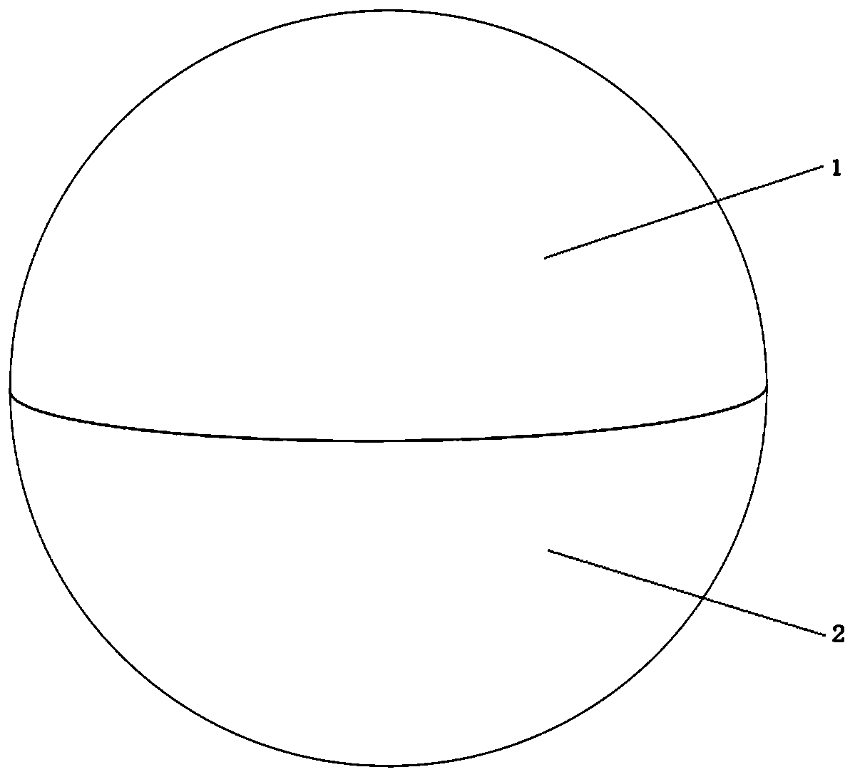
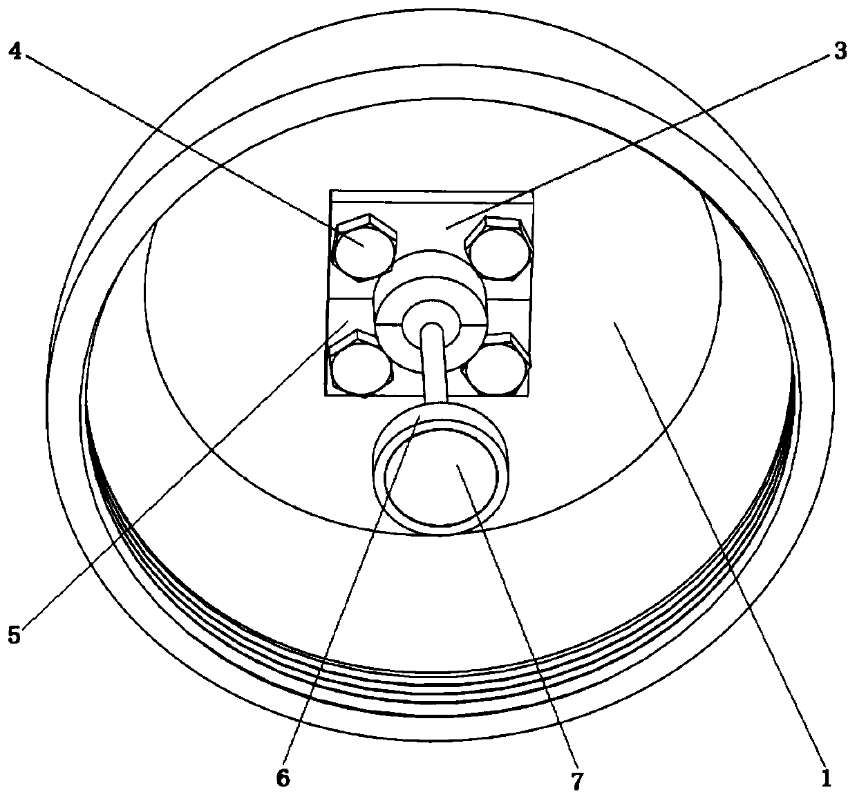
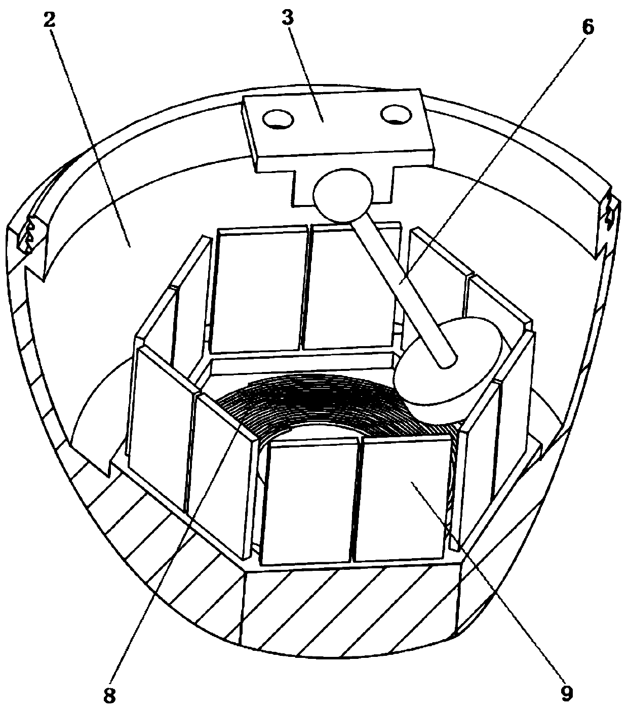
[0025] An omnidirectional piezoelectric electromagnetic composite wave energy collection device, the spherical shell is divided into an upper shell 1 and a lower shell 2, and the openings of the upper shell 1 and the lower shell 2 are provided with mutually matching threads; the upper shell The inner top surface of the body 1 is a plane and is provided with four threaded holes. The upper parts of the left spherical hinge seat 3 and the right spherical hinge seat 5 are both flat plates with a pair of screw hole structures, and the lower parts have hemispherical cavities. The upper part of the pendulum of the hammer 6 is a spherical body, and the lower part is a round cake-shaped structure. The lower surface of the round cake-shaped structure is inlaid with a circular permanent magnet 7; The hemispherical cavity fits together and is fix...


PUM


Abstract

The invention provides an omnidirectional piezoelectricity electromagnetic composite wave energy acquiring device, and belongs to the field of energy collecting device designing and manufacturing. A spherical housing is divided into an upper shell and a lower shell, wherein threads which are in mutual cooperation are formed in the openings of the upper shell and the lower shell; the top surface ofthe inner part of the upper shell is a plane, and is provided with four threaded holes; the upper parts of a left spherical hinging seat and a right spherical hinging seat are slabs and are providedwith a pair of screw hole structure, and the lower parts of the left spherical hinging seat and the right spherical hinging seat are provided with a semispherical cavity; the upper part of a pendulumswinging rod is a spherical body, and the lower part of the pendulum swinging rod adopts a round cake shaped structure; a circular permanent magnet is embedded on the lower surface of the round cake shaped structure; the spherical body at the upper part is fixed to the top surface in the upper shell through the clearance fit of the two combined semispherical cavities in the lower parts of the leftspherical hinging seat and the right spherical hinging seat; a part of which the height is one third of that of the inner part of the lower shell, of the lower shell is a plane formed by a solid sphere; grooves which are formed in a regular hexagon shape are annularly formed; the lower parts of bimorph piezoelectricity pieces are embedded in the grooves; and a copper coil is embedded on a plane in the lower shell.

Description

technical field [0001] The invention belongs to the field of design and manufacture of energy harvesting devices. Background technique [0002] With the gradual increase of energy consumption, the problem of energy shortage has become a hot spot that everyone pays attention to. In order to solve the energy problem, energy harvesting technology has been extensively studied, and it is hoped that by harvesting the energy present in the environment, it can be used to power various electronic devices. With 70 percent of the Earth's surface covered by oceans, blue energy holds great promise for powering wireless sensors. Wave energy is one of the main sources of blue energy, which represents the energy provided by water waves, tides, and oceans. The wave is characterized by random and irregular vibrations, and its ultra-low frequency is less than 10hz, or even 1hz. There are three main methods of converting wave energy into electricity: electromagnetic, piezoelectric, and mecha...

Claims


Application Information

Patent Timeline
IPC IPC(8): F03B13/18H02K35/02H02N2/18H02J7/32
CPCF03B13/18F05B2220/709H02J7/32H02K35/02H02N2/186Y02E10/30
Inventor 张祖涛王伟郑鹏陈江帆袁艳平罗大兵潘亚嘉
Owner SOUTHWEST JIAOTONG UNIV
Why Eureka
Try Eureka