Combined multi-way valve and combined multi-way valve control system

A control system and multi-way valve technology, applied in the direction of servo meter circuit, servo motor assembly, servo motor, etc., can solve problems such as incoordination, unstable action of actuators, unstable load feedback pressure, etc., to achieve stable action and solve problems. Execute the effect of structural delay or large shock vibration and best operational performance

Active Publication Date: 2020-05-15
中联重科土方机械有限公司
View PDF2 Cites 3 Cited by
  • Summary
  • Abstract
  • Description
  • Claims
  • Application Information

AI Technical Summary

Problems solved by technology

[0008] The purpose of the embodiment of the present invention is to propose a combined multi-way valve and a combined multi-way valve control system on the basis of the existing load-sensitive multi-way valve, which can solve the problem

Method used


Image

  • Combined multi-way valve and combined multi-way valve control system
  • Combined multi-way valve and combined multi-way valve control system
  • Combined multi-way valve and combined multi-way valve control system

Examples


Embodiment Construction

[0038] Specific embodiments of the present invention will be described in detail below in conjunction with the accompanying drawings. It should be understood that the specific embodiments described here are only used to illustrate and explain the present invention, and are not intended to limit the present invention.

[0039] In the embodiments of the present invention, unless stated otherwise, the used orientation words such as "up, down, top, bottom" are usually for the directions shown in the drawings or for vertical, vertical or The term used to describe the mutual positional relationship of each component in terms of the direction of gravity.

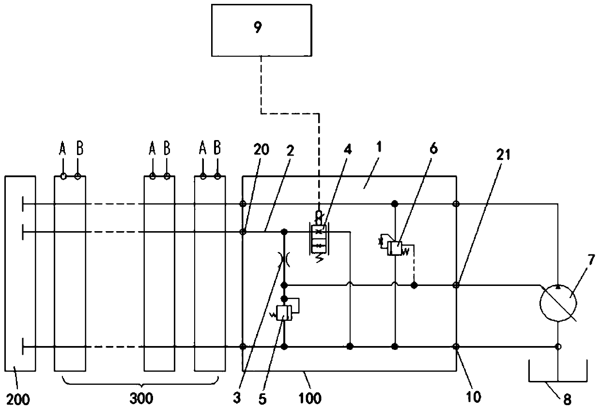
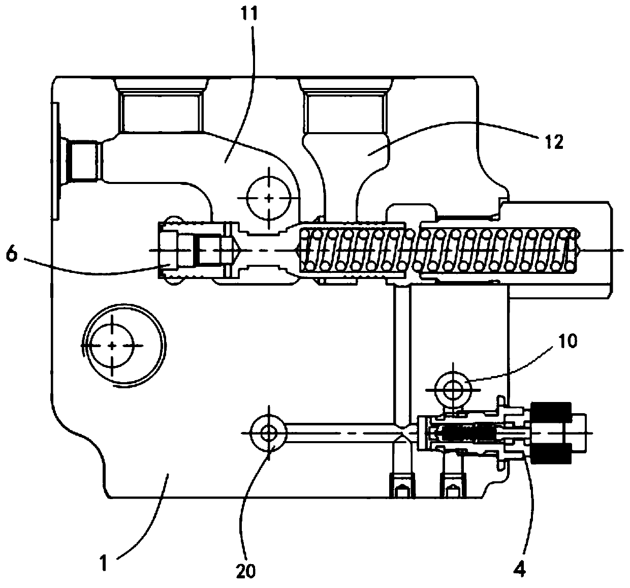
[0040] figure 1 It is the working principle diagram of the combined multi-way valve provided by the embodiment of the present invention; figure 2 It is the front view of the combined multi-way valve provided by the embodiment of the present invention.

[0041] In one aspect of the present invention, a combined multi-way valve i...


PUM


Abstract

A combined multi-way valve comprises a head unit, a tail unit and a plurality of sets of working units. Each working unit is provided with a set of paired working oil port A and working oil port B. The head unit comprises a valve body, a valve element and a feedback channel. A first cavity and a second cavity are formed in the valve body. A first feedback port of the feedback channel selectively communicates with a set of working oil port A and working oil port B, and a second feedback port of the feedback channel is connected with an external variable pump. A throttle valve is mounted on thefeedback channel to transmit load feedback pressure of each working oil port A or working oil port B to the external variable pump. An electric proportional flow valve is mounted between the first feedback channel and an oil return port of the valve body to adjust load feedback pressure in the feedback channel. The invention further provides a combined multi-way valve control system. According tothe combined multi-way valve and the combined multi-way valve control system, the electric proportional flow valve is used to stabilize the load feedback pressure in the feedback channel in the combined multi-way valve, so that output flow of the external variable pump is stable, and it is ensured that an executing mechanism is harmony in action, stable and good in operating performance.

Description

technical field [0001] The invention relates to the field of engineering machinery, in particular to a combined multi-way valve and a combined multi-way valve control system. Background technique [0002] In the field of construction machinery, especially in excavators, load-sensitive multi-way valves are widely used. The actuators of excavators are mainly driven by hydraulic cylinders and hydraulic motors. During excavation operations, it is necessary to distribute flow to different actuators. At present, in excavators A load-sensing system is used for flow distribution control. The load-sensing system is composed of a load-sensing multi-way valve and a load-sensing pump to realize flow distribution. The load-sensing valve feeds back the highest pressure of multiple loads to the load-sensing pump through the load feedback oil circuit, and adjusts the load-sensing pressure signal according to the load-feedback pressure signal. The displacement of the pump to output the flow...

Claims


Application Information

Patent Timeline
IPC IPC(8): F15B13/02F15B11/00E02F9/22
CPCE02F9/2267F15B11/00F15B13/02F15B2013/002F15B2211/20546
Inventor 周启迪刘象宝陈华波杨阳
Owner 中联重科土方机械有限公司
Why Eureka
Try Eureka