
Drying heat recycling device for leather production

A heat recovery device, leather technology, applied in drying, dryer, drying gas arrangement and other directions, can solve the problems of uneven surface cells, poor folding resistance and peeling performance, consumer harm, etc., and achieve molding effect Stable, guaranteed stability, energy saving effect

Inactive Publication Date: 2020-05-15
HUAIAN KAIYUE TECH DEV
View PDF0 Cites 1 Cited by
  • Summary
  • Abstract
  • Description
  • Claims
  • Application Information

AI Technical Summary

Problems solved by technology

[0002] In the production process of polyurethane PU synthetic leather, the coating process is involved. The composite slurry is coated on the base fabric, and the base fabric coated with the composite slurry needs to be dried. The traditional composite slurry is oily resin slurry. , Oleoresin contains a large amount of toxic and harmful gases, which will cause great harm to the environment and operators, and the synthetic leather made of oleoresin coating will also contain toxic and harmful substances, which will also cause harm to consumers, so The existing technology has begun to use non-toxic and harmless water-based resin for base cloth coating, but because the water-based resin contains a large amount of water molecules, the traditional oven equipment is not enough to meet the drying requirements. Drying equipment for water-based resin drying, but most of this type of equipment structure is designed as a front and rear heating chamber, the general temperature gradient is 60-70°C, and then directly rises to 100-140°C, the problem with this design is the final synthesis Due to the fast water loss of leather, the surface cells are uneven, and the folding resistance and peeling performance are poor; in addition, during the coating process, the base fabric is conveyed forward by the needle conveyor belt, and the needles will inevitably fall off during the conveying process. Situation of Kib

Method used


Image

  • Drying heat recycling device for leather production
  • Drying heat recycling device for leather production
  • Drying heat recycling device for leather production

Examples


Embodiment Construction

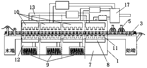
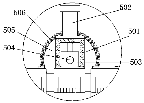
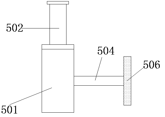
[0028] In order to make the technical means, creative features, goals and effects achieved by the present invention easy to understand, the present invention will be further described below in conjunction with specific embodiments.

[0029] like Figure 1-8 As shown, a drying heat recovery device for leather production includes a conveying mechanism 2 arranged inside an oven 1, and the conveying mechanism 2 is composed of two sets of symmetrically distributed needle conveyor belts 3 (see Figure 4 , Figure 4 is also the conveying direction of the base cloth), the needle conveyor belt 3 is placed on the working frame, the needle conveyor belt 3 includes a chain 31, and the supporting plates 32 are equidistantly distributed on the chain 31, and the upper edge of the supporting plate 32 is locked by two bolts. In the threaded holes on the two pin shafts of the same section of the chain 31, there are many vertical needles 14 welded along the plate under the supporting plate 32. ...


PUM

PropertyMeasurementUnit
lengthaaaaaaaaaa

Abstract

The invention discloses a drying heat recycling device for leather production. The drying heat recycling device comprises a conveying mechanism arranged in a drying box, the conveying mechanism is composed of two sets of symmetrically-distributed needle conveying belts, supporting plates are arranged between the positions, arranged on the outer side of the drying box, of the initial ends of each set of needle conveying belts, and the supporting plates are fixedly connected with at least one pressing device; the interior of the drying box is provided with at least three drying inner cavities; and the position corresponding to each drying inner cavity, the top end of the drying box is provided with an air exhaust pipe. The existing two-cavity structure design is broken through, temperature gradient is achieved through the multiple cavities, meanwhile, along with increasing of the quantity of the drying inner cavities, harmful waste gas and water vapor exhausted from the corresponding airexhaust pipes are processed in the first several drying inner cavities, and hot gas exhausted from the Nth air exhaust pipe of the drying inner cavity at the tail end can be transmitted into the airexhaust pipe in the drying inner cavity A at the initial end through a pipeline to be used for preliminary drying.

Description

technical field [0001] The invention relates to a heat recovery device, in particular to a drying heat recovery device for leather production. Background technique [0002] In the production process of polyurethane PU synthetic leather, the coating process is involved. The composite slurry is coated on the base fabric, and the base fabric coated with the composite slurry needs to be dried. The traditional composite slurry is oily resin slurry. , Oleoresin contains a large amount of toxic and harmful gases, which will cause great harm to the environment and operators, and the synthetic leather made of oleoresin coating will also contain toxic and harmful substances, which will also cause harm to consumers, so The existing technology has begun to use non-toxic and harmless water-based resin for base cloth coating, but because the water-based resin contains a large amount of water molecules, the traditional oven equipment is not enough to meet the drying requirements. Drying e...

Claims


Application Information

Patent Timeline
Patent Type & Authority Applications(China)
IPC IPC(8): F26B15/18F26B21/04F26B25/00B05D3/04D06N3/00
CPCB05D3/0413D06N3/0077F26B15/18F26B21/04F26B25/00F26B25/005Y02P70/10Y02P70/62
Inventor 李桂军李浩扬
Owner HUAIAN KAIYUE TECH DEV
Learn More